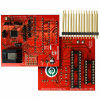
AC162078 Microchip Technology, AC162078 Datasheet - Page 143

AC162078
Manufacturer Part Number
AC162078
Description
HEADER INTRFC MPLAB ICD2 18F1330
Manufacturer
Microchip Technology
Datasheet
1.AC162078.pdf
(318 pages)
Specifications of AC162078
Accessory Type
Transition Header
Lead Free Status / RoHS Status
Not applicable / Not applicable
For Use With/related Products
ICD2
Lead Free Status / RoHS Status
Lead free / RoHS Compliant, Not applicable / Not applicable
Available stocks
Company
Part Number
Manufacturer
Quantity
Price
Company:
Part Number:
AC162078
Manufacturer:
MICROCHIP
Quantity:
12 000
- Current page: 143 of 318
- Download datasheet (3Mb)
14.12.2
The FLTAMOD bit in the FLTCONFIG register
determines whether the PWM I/O pins are deactivated
when they are overridden by a Fault input.
FLTAS bit in the FLTCONFIG register gives the status
of the Fault A input.
The Fault input has two modes of operation:
• Inactive Mode (FLTAMOD = 0)
• Cycle-by-Cycle Mode (FLTAMOD = 1)
REGISTER 14-8:
2009 Microchip Technology Inc.
bit 7
Legend:
R = Readable bit
-n = Value at POR
bit 7
bit 6-3
bit 2
bit 1
bit 0
This is a catastrophic Fault Management mode.
When the Fault occurs in this mode, the PWM
outputs are deactivated. The PWM pins will remain in
Inactivated mode until the Fault is cleared (Fault
input is driven high) and the corresponding Fault
status bit has been cleared in software. The PWM
outputs are enabled immediately at the beginning of
the following PWM period, after Fault status bit
(FLTAS) is cleared.
When the Fault occurs in this mode, the PWM
outputs are deactivated. The PWM outputs will
remain in the defined Fault states (all PWM outputs
inactive) for as long as the Fault pin is held low. After
the Fault pin is driven high, the PWM outputs will
return to normal operation at the beginning of the
following PWM period and the FLTAS bit is
automatically cleared.
BRFEN
R/W-0
FAULT INPUT MODE
BRFEN: Breakpoint Fault Enable bit
1 = Enable Fault condition on a breakpoint
0 = Disable Fault condition
Unimplemented: Read as ‘0’
FLTAS: Fault A Status bit
1 = FLTA is asserted:
0 = No Fault
FLTAMOD: Fault A Mode bit
1 = Cycle-by-Cycle mode: Pins are inactive for the remainder of the current PWM period or until FLTA
0 = Inactive mode: Pins are deactivated (catastrophic failure) until FLTA is deasserted and FLTAS is
FLTAEN: Fault A Enable bit
1 = Enable Fault A
0 = Disable Fault A
if FLTAMOD = 0, cleared by the user;
if FLTAMOD = 1, cleared automatically at beginning of the new period when FLTA is deasserted
is deasserted; FLTAS is cleared automatically
cleared by the user only
U-0
—
FLTCONFIG: FAULT CONFIGURATION REGISTER
W = Writable bit
‘1’ = Bit is set
U-0
—
U-0
—
U = Unimplemented bit, read as ‘0’
‘0’ = Bit is cleared
14.12.3
While in the Fault state (i.e., FLTA input is active), the
PWM output signals are driven into their inactive
states.
14.12.4
The BRFEN bit in the FLTCONFIG register controls the
simulation of Fault condition when a breakpoint is hit,
while debugging the application using an In-Circuit
Debugger (ICD). Setting the BRFEN bit to high enables
the Fault condition on breakpoint, thus driving the PWM
outputs to inactive state. This is done to avoid any
continuous keeping of status on the PWM pin, which
may result in damage of the power devices connected
to the PWM outputs.
If BRFEN = 0, the Fault condition on breakpoint is
disabled.
U-0
—
Note:
PIC18F1230/1330
PWM OUTPUTS WHILE IN FAULT
CONDITION
PWM OUTPUTS IN DEBUG MODE
It is highly recommended to enable the
Fault
debugging tool is used while developing
the firmware and the high-power circuitry
is used. When the device is ready to
program after debugging the firmware, the
BRFEN bit can be disabled.
FLTAS
R/W-0
condition
x = Bit is unknown
FLTAMOD
R/W-0
on
DS39758D-page 143
breakpoint
FLTAEN
R/W-0
if
bit 0
a
Related parts for AC162078
Image
Part Number
Description
Manufacturer
Datasheet
Request
R

Part Number:
Description:
Manufacturer:
Microchip Technology Inc.
Datasheet:

Part Number:
Description:
Manufacturer:
Microchip Technology Inc.
Datasheet:

Part Number:
Description:
Manufacturer:
Microchip Technology Inc.
Datasheet:

Part Number:
Description:
Manufacturer:
Microchip Technology Inc.
Datasheet:

Part Number:
Description:
Manufacturer:
Microchip Technology Inc.
Datasheet:

Part Number:
Description:
Manufacturer:
Microchip Technology Inc.
Datasheet:

Part Number:
Description:
Manufacturer:
Microchip Technology Inc.
Datasheet:

Part Number:
Description:
Manufacturer:
Microchip Technology Inc.
Datasheet:


