AC162078 Microchip Technology, AC162078 Datasheet - Page 21
AC162078
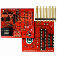
Manufacturer Part Number
AC162078
Description
HEADER INTRFC MPLAB ICD2 18F1330
Manufacturer
Microchip Technology
Datasheet
1.AC162078.pdf
(318 pages)
Specifications of AC162078
Accessory Type
Transition Header
Lead Free Status / RoHS Status
Not applicable / Not applicable
For Use With/related Products
ICD2
Lead Free Status / RoHS Status
Lead free / RoHS Compliant, Not applicable / Not applicable
Available stocks
Company
Part Number
Manufacturer
Quantity
Price
Company:

Part Number:
AC162078
Manufacturer:
MICROCHIP
Quantity:
12 000


3.0
3.1
PIC18F1230/1330 devices can be operated in ten
different oscillator modes. The user can program the
Configuration bits, FOSC3:FOSC0, in Configuration
Register 1H to select one of these ten modes:
1.
2.
3.
4.
5.
6.
7.
8.
9.
10. ECIO
3.2
In XT, LP, HS or HSPLL Oscillator modes, a crystal or
ceramic resonator is connected to the OSC1 and
OSC2 pins to establish oscillation. Figure 3-1 shows
the pin connections.
The oscillator design requires the use of a parallel
resonant crystal.
2009 Microchip Technology Inc.
Note:
LP
XT
HS
HSPLL High-Speed Crystal/Resonator
RC
RCIO
INTIO1 Internal Oscillator with F
INTIO2 Internal Oscillator with I/O on RA6
EC
OSCILLATOR
CONFIGURATIONS
Oscillator Types
Crystal Oscillator/Ceramic
Resonators
Use of a series resonant crystal may give
a
manufacturer’s specifications.
Low-Power Crystal
Crystal/Resonator
High-Speed Crystal/Resonator
with PLL enabled
External Resistor/Capacitor with
F
External Resistor/Capacitor with I/O
on RA6
on RA6 and I/O on RA7
and RA7
External Clock with F
External Clock with I/O on RA6
OSC
frequency
/4 output on RA6
out
OSC
of
OSC
/4 output
the
/4 output
crystal
FIGURE 3-1:
TABLE 3-1:
Capacitor values are for design guidance only.
Different capacitor values may be required to produce
acceptable oscillator operation. The user should test
the performance of the oscillator over the expected
V
See the notes following Table 3-2 for additional
information.
Note 1: See Table 3-1 and Table 3-2 for initial values of
DD
Mode
XT
and temperature range for the application.
C1
C2
2: A series resistor (R
3: R
PIC18F1230/1330
(1)
(1)
Typical Capacitor Values Used:
C1 and C2.
strip cut crystals.
F
3.58 MHz
4.19 MHz
XTAL
R
varies with the oscillator mode chosen.
4 MHz
4 MHz
S
Freq
(2)
CAPACITOR SELECTION FOR
CERAMIC RESONATORS
OSC2
OSC1
CRYSTAL/CERAMIC
RESONATOR OPERATION
(XT, LP, HS OR HSPLL
CONFIGURATION)
S
OSC1
15 pF
15 pF
30 pF
50 pF
) may be required for AT
R
F
(3)
DS39758D-page 21
PIC18FXXXX
Sleep
To
OSC2
15 pF
15 pF
30 pF
50 pF
Internal
Logic
Related parts for AC162078
Image
Part Number
Description
Manufacturer
Datasheet
Request
R

Part Number:
Description:
Manufacturer:
Microchip Technology Inc.
Datasheet:
Part Number:
Description:
Manufacturer:
Microchip Technology Inc.
Datasheet:
Part Number:
Description:
Manufacturer:
Microchip Technology Inc.
Datasheet:
Part Number:
Description:
Manufacturer:
Microchip Technology Inc.
Datasheet:
Part Number:
Description:
Manufacturer:
Microchip Technology Inc.
Datasheet:
Part Number:
Description:
Manufacturer:
Microchip Technology Inc.
Datasheet:
Part Number:
Description:
Manufacturer:
Microchip Technology Inc.
Datasheet:
Part Number:
Description:
Manufacturer:
Microchip Technology Inc.
Datasheet: