AC162078 Microchip Technology, AC162078 Datasheet - Page 206
AC162078
Manufacturer Part Number
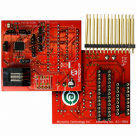
AC162078
Description
HEADER INTRFC MPLAB ICD2 18F1330
Manufacturer
Microchip Technology
Datasheet
1.AC162078.pdf
(318 pages)
Specifications of AC162078
Accessory Type
Transition Header
Lead Free Status / RoHS Status
Not applicable / Not applicable
For Use With/related Products
ICD2
Lead Free Status / RoHS Status
Lead free / RoHS Compliant, Not applicable / Not applicable
Available stocks
Company
Part Number
Manufacturer
Quantity
Price
Company:

Part Number:
AC162078
Manufacturer:
MICROCHIP
Quantity:
12 000


managed clock source resumes in the power-managed
PIC18F1230/1330
FIGURE 20-4:
20.4.3
By entering a power-managed mode, the clock multi-
plexer selects the clock source selected by the OSCCON
register. Fail-Safe Clock Monitoring of the power-
mode.
If an oscillator failure occurs during power-managed
operation, the subsequent events depend on whether
or not the oscillator failure interrupt is enabled. If
enabled (OSCFIF = 1), code execution will be clocked
by the INTOSC multiplexer. An automatic transition
back to the failed clock source will not occur.
If the interrupt is disabled, subsequent interrupts while
in Idle mode will cause the CPU to begin executing
instructions while being clocked by the INTOSC
source.
20.4.4
The FSCM is designed to detect oscillator failure at any
point after the device has exited Power-on Reset
(POR) or low-power Sleep mode. When the primary
device clock is EC, RC or INTRC modes, monitoring
can begin immediately following these events.
For oscillator modes involving a crystal or resonator
(HS, HSPLL, LP or XT), the situation is somewhat
different. Since the oscillator may require a start-up
DS39758D-page 206
Note:
Sample Clock
CM Output
FSCM INTERRUPTS IN
POWER-MANAGED MODES
POR OR WAKE FROM SLEEP
OSCFIF
Device
Output
Clock
The device clock is normally at a much higher frequency than the sample clock. The relative frequencies in
this example have been chosen for clarity.
(Q)
FSCM TIMING DIAGRAM
CM Test
time considerably longer than the FCSM sample clock
time, a false clock failure may be detected. To prevent
this, the internal oscillator block is automatically
configured as the device clock and functions until the
primary clock is stable (the OST and PLL timers have
timed out). This is identical to Two-Speed Start-up
mode. Once the primary clock is stable, the INTRC
returns to its role as the FSCM source.
As noted in Section 20.3.1 “Special Considerations
for Using Two-Speed Start-up”, it is also possible to
select another clock configuration and enter an
alternate power-managed mode while waiting for the
primary clock to become stable. When the new power-
managed mode is selected, the primary clock is
disabled.
Note:
CM Test
Oscillator
Failure
The same logic that prevents false oscilla-
tor failure interrupts on POR, or wake from
Sleep, will also prevent the detection of
the oscillator’s failure to start at all follow-
ing these events. This can be avoided by
monitoring the OSTS bit and using a
timing routine to determine if the oscillator
is taking too long to start. Even so, no
oscillator failure interrupt will be flagged.
2009 Microchip Technology Inc.
Detected
Failure
CM Test
Related parts for AC162078
Image
Part Number
Description
Manufacturer
Datasheet
Request
R

Part Number:
Description:
Manufacturer:
Microchip Technology Inc.
Datasheet:
Part Number:
Description:
Manufacturer:
Microchip Technology Inc.
Datasheet:
Part Number:
Description:
Manufacturer:
Microchip Technology Inc.
Datasheet:
Part Number:
Description:
Manufacturer:
Microchip Technology Inc.
Datasheet:
Part Number:
Description:
Manufacturer:
Microchip Technology Inc.
Datasheet:
Part Number:
Description:
Manufacturer:
Microchip Technology Inc.
Datasheet:
Part Number:
Description:
Manufacturer:
Microchip Technology Inc.
Datasheet:
Part Number:
Description:
Manufacturer:
Microchip Technology Inc.
Datasheet: