AC162078 Microchip Technology, AC162078 Datasheet - Page 91
AC162078
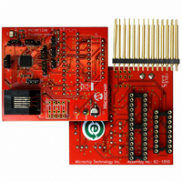
Manufacturer Part Number
AC162078
Description
HEADER INTRFC MPLAB ICD2 18F1330
Manufacturer
Microchip Technology
Datasheet
1.AC162078.pdf
(318 pages)
Specifications of AC162078
Accessory Type
Transition Header
Lead Free Status / RoHS Status
Not applicable / Not applicable
For Use With/related Products
ICD2
Lead Free Status / RoHS Status
Lead free / RoHS Compliant, Not applicable / Not applicable
Available stocks
Company
Part Number
Manufacturer
Quantity
Price
Company:

Part Number:
AC162078
Manufacturer:
MICROCHIP
Quantity:
12 000


TABLE 10-3:
2009 Microchip Technology Inc.
RB0/PWM0
RB1PWM1
RB2/INT2/KBI2/
CMP2/T1OSO/
T1CKI
RB3/INT3/KBI3/
CMP1/T1OSI
RB4/PWM2
RB5/PWM3
RB6/PWM4/PGC
RB7/PWM5/PGD
Legend:
Note 1:
Pin
2:
DIG = Digital level output; TTL = TTL input buffer; ST = Schmitt Trigger input buffer; ANA = Analog level input/output;
x = Don’t care (TRIS bit does not affect port direction or is overridden for this option).
Configuration on POR is determined by the PBADEN Configuration bit. Pins are configured as analog inputs by default
when PBADEN is set and digital inputs when PBADEN is cleared.
Placement of T1OSI and T1OSO/T1CKI depends on the value of Configuration bit, T1OSCMX, of CONFIG3H.
PORTB I/O SUMMARY
T1OSO
Function
T1OSI
T1CKI
PWM0
PWM1
PWM2
PWM3
PWM4
PWM5
CMP2
CMP1
KBI2
KBI3
INT2
INT3
PGC
PGD
RB0
RB1
RB2
RB3
RB4
RB5
RB6
RB7
(2)
(2)
(2)
Setting
TRIS
0
1
0
0
1
0
0
1
1
1
1
0
1
0
1
1
1
1
1
0
1
0
0
1
0
0
1
0
1
0
1
0
0
I/O
O
O
O
O
O
O
O
O
O
O
O
O
O
O
O
O
I
I
I
I
I
I
I
I
I
I
I
I
I
I
I
I
I
Type
ANA
ANA
ANA
ANA
DIG
TTL
DIG
DIG
TTL
DIG
DIG
TTL
TTL
DIG
TTL
TTL
DIG
TTL
DIG
DIG
TTL
DIG
DIG
TTL
DIG
DIG
TTL
TTL
DIG
I/O
ST
ST
ST
ST
LATB<0> data output; not affected by analog input.
PORTB<0> data input; weak pull-up when RBPU bit is cleared.
Disabled when analog input enabled.
PWM module output PWM0.
LATB<1> data output; not affected by analog input.
PORTB<1> data input; weak pull-up when RBPU bit is cleared.
Disabled when analog input enabled.
PWM module output PWM1.
LATB<2> data output; not affected by analog input.
PORTB<2> data input; weak pull-up when RBPU bit is cleared.
Disabled when analog input enabled.
External interrupt 2 input.
Interrupt-on-change pin.
Comparator 2 input.
Timer1 oscillator output.
Timer1 clock input.
LATB<3> data output; not affected by analog input.
PORTB<3> data input; weak pull-up when RBPU bit is cleared.
Disabled when analog input enabled.
External interrupt 3 input.
Interrupt-on-change pin.
Comparator 1 input.
Timer1 oscillator input.
LATB<4> data output; not affected by analog input.
PORTB<4> data input; weak pull-up when RBPU bit is cleared.
Disabled when analog input enabled.
PWM module output PWM2.
LATB<5> data output.
PORTB<5> data input; weak pull-up when RBPU bit is cleared.
PWM module output PWM3.
LATB<6> data output.
PORTB<6> data input; weak pull-up when RBPU bit is cleared.
PWM module output PWM4.
In-Circuit Debugger and ICSP™ programming clock pin.
LATB<7> data output.
PORTB<7> data input; weak pull-up when RBPU bit is cleared.
PWM module output PWM4.
In-Circuit Debugger and ICSP programming data pin.
PIC18F1230/1330
Description
(1)
(1)
(1)
(1)
(1)
DS39758D-page 91
Related parts for AC162078
Image
Part Number
Description
Manufacturer
Datasheet
Request
R

Part Number:
Description:
Manufacturer:
Microchip Technology Inc.
Datasheet:
Part Number:
Description:
Manufacturer:
Microchip Technology Inc.
Datasheet:
Part Number:
Description:
Manufacturer:
Microchip Technology Inc.
Datasheet:
Part Number:
Description:
Manufacturer:
Microchip Technology Inc.
Datasheet:
Part Number:
Description:
Manufacturer:
Microchip Technology Inc.
Datasheet:
Part Number:
Description:
Manufacturer:
Microchip Technology Inc.
Datasheet:
Part Number:
Description:
Manufacturer:
Microchip Technology Inc.
Datasheet:
Part Number:
Description:
Manufacturer:
Microchip Technology Inc.
Datasheet: