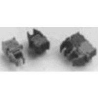
HFBR-0528 Avago Technologies US Inc., HFBR-0528 Datasheet - Page 10

HFBR-0528
Manufacturer Part Number
HFBR-0528
Description
KIT EVAL FIBER OPTIC 10MBD
Manufacturer
Avago Technologies US Inc.
Datasheet
1.HFBR-0528.pdf
(16 pages)
Specifications of HFBR-0528
Main Purpose
Interface, Fiber Optics
Embedded
No
Utilized Ic / Part
HFBR-1528, HFBR-2528
Primary Attributes
10MBd, Communication up to 50m using 1mm POF
Secondary Attributes
Crimpless Connectors
Silicon Core Number
HFBR-1528, HFBR-2528
Kit Contents
TX/RX Mods, Cable, Pol Kit, SW, Pwr. Sup
Silicon Family Name
Versatile Link
Features
Fiber Optic Transmitter And Receiver
Lead Free Status / RoHS Status
Lead free / RoHS Compliant
Other names
516-2144
HFBR-0528
HFBR-0528
Figure 6 also shows that as Vcc increases, the total vari-
ation in LED forward current, due to other circuit toler-
ances, is minimized.
The recommended LED driver shown in Figure 9 takes
advantage of the negative temperature coefficient of
the HFBR-528Z LED forward voltage. When tempera-
ture rises, the forward voltage of the LED decreases and
a greater percentage of the supply potential must be
dropped across resistor R2. As temperature increases
and LED forward voltage declines, the potential differ-
ence across R2 increases and Ohm’s law dictates that the
current through R2 and the HFBR-528Z will increase.
This increase in the drive current partially equalizes the
reduced light output due to the negative output-power
temperature coefficient.
The coupled power into mm POF and 200 µm HCS is
specified for minimum and maximum values versus the
temperature range for 20 mA and 60 mA. Intermediate
power levels can be calculated based on Figure 2 in the
HFBR-528Z data sheet. At drive currents less than speci-
fied in the data sheet, the part-to-part variation of the
output power increases.
Figure 16. Output Power Variation vs. Supply Voltage and Components
Tolerances.
2.3. The Simplest LED Trans-mitter Shunt Drive Circuit
The circuit shown in Figure 4 is a simple-shunt drive
transmitter circuit that uses a pnp transistor. The primary
feature is its simplicity: only two components are re-
quired and the circuit can be interfaced to TTL or CMOS
gates without additional components. The circuit is also
fast for several reasons:
• the transistor never saturates,
• it presents a very low impedance during turn off of
• the emitter base junction voltage “prebiases” the LED
0
5
the LED, and
junction resulting in a faster optical rise time
1.2
1.1
1.0
0.9
0.8
0
TOLERANCES
V f : ±15%; V ce : ±75%, R: ±1%
5
10
V
CC
10
V
CC
(VOLTS)
(VOLTS)
MAXIMUM
15
MINIMUM
MAXIMUM
15
MINIMUM
20
25
20
5510-17
25
In addition, the pnp drive circuit generates low power-
supply ripple because of the constant load during LED
switching. The drawback is increased power consump-
tion due to the constant current flow through the bias
resistor.
Figure 17. Switching Speed vs. Drive Current.
3. Receiver Interface Circuit Design
The HFBR-2528Z receiver has a push/pull digital output.
It is capable of sourcing and sinking current as high as
±6 mA (receivers HFBR-25XZ,2Z,3Z,4Z need pull-up
resistors) and can drive CMOS and TTL logic families
without external resistors. Avago Technologies recom-
mends that an RC first-order, low-pass filter (see Figure
9) be used to minimize the power-supply noise between
the ground and power supply terminals of the receiver.
This arrangement will meet the power-supply rejection
specification. The bypass capacitor should be connected
as close as possible to the power supply terminals of the
HFBR-2528Z receiver. A ground plane underneath the
conductive receiver housing and connected to pins 5
and 8 provides an excellent shield against electric fields
as high as 8 kV/m, which could otherwise interfere with
the receiver IC.
3.1. Sensitivity
DC-coupled receivers, such as the HFBR-2528Z, are
specified for sensitivity at different conditions than ac-
coupled receivers
an important criterion. For the HFBR-2528Z, sensitivity is
the minimum optical power level for a PWD of less than
|30| ns, measured with a 50 percent duty cycle, square-
wave signal.
3.2. Off-State-Limit
Avago Technologies recommends that no light be cou-
pled to the receiver when it should remain in the logic-
high state. In some instances, it might not be possible to
turn the transmitter totally off. But the power delivered
to the receiver should be always less than -42 dBm for
mm POF or -44 dBm for 200 µm HCS fibers to ensure that
the output does not randomly change state.
20
15
10
1 mm POF
5
0
I
20
F -
FORWARD CURRENT T HROUGH LE D ( m A)
30
t ( r ) ( ns )
40 m , DC =
PWD (%)
20
15
10
5
0
20
I
F -
1 mm POF 40 m, DC = 49.7%, f = 7.5 MHz
FORWARD CURRENT THROUGH LED (mA)
40
30
[3]
t(r) (ns)
PWD (%)
in which the bit-error ratio (BER) is
40
49.7%, f =
50
50
t(f) (ns)
60
t ( f ) ( ns )
60
70
50
45
40
7.5 MH z
70
50
45
40


