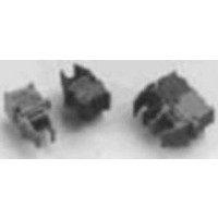
HFBR-0528 Avago Technologies US Inc., HFBR-0528 Datasheet - Page 7

HFBR-0528
Manufacturer Part Number
HFBR-0528
Description
KIT EVAL FIBER OPTIC 10MBD
Manufacturer
Avago Technologies US Inc.
Datasheet
1.HFBR-0528.pdf
(16 pages)
Specifications of HFBR-0528
Main Purpose
Interface, Fiber Optics
Embedded
No
Utilized Ic / Part
HFBR-1528, HFBR-2528
Primary Attributes
10MBd, Communication up to 50m using 1mm POF
Secondary Attributes
Crimpless Connectors
Silicon Core Number
HFBR-1528, HFBR-2528
Kit Contents
TX/RX Mods, Cable, Pol Kit, SW, Pwr. Sup
Silicon Family Name
Versatile Link
Features
Fiber Optic Transmitter And Receiver
Lead Free Status / RoHS Status
Lead free / RoHS Compliant
Other names
516-2144
HFBR-0528
HFBR-0528
Equation III/2:
P
P
α(min): Minimum attenuation of fiber (dB/m)
The extremely large dynamic range of the HFBR-2528Z
receiver typically allows room-temperature distances
from 0 to 00 meters when using mm plastic fibers.
Typically, LED current adjustments are not needed as the
length of the plastic fiber can vary from 0 to 00 meters
at room temperature, and the maximum adjustment-
free distances possible over the temperature range are
IL(dB) = 20
specified in the HFBR-0508Z series data sheet.
1.3 Temperature Drift Considerations
The data sheet includes the transmitter output power
range for ambient temperatures at T
+70°C, and T
anteed link length specifications. But by knowing and
understanding all different temperature drift effects that
the link depends on, the design engineer will be able to
optimize the link performance, particularly, the maxi-
mum fiber length.
The output power of the transmitter is inversely propor-
tional to the junction temperature, resulting in a lower
output power at high temperatures (∆P
Equation III/3:
P
P
the data sheet (dBm)
∆P
The forward voltage (∆V
an increase in temperature, causing an increase of drive
current, which partially compensates for the decreasing
output power.
Equation III/4:
V
IL(dB) = 20
V
∆P
7
P (T) = P (25) –
P (dBm) = 10
l(max) =
P (T) = P (25) –
IL(dB) = 20
l(min) =
l(max) =
P (T) = P (25) –
l(min) =
P (dBm) = 10
T
RL, (max)
l =
T
T
F
F
l =
V (T) = V (25)
R1 =
l(min) =
V (T) = V (25)
R1 =
T
T
l =
(max): Maximum coupled power of transmitter (dBm)
(T): Output power at desired temperature (dBm)
(25): Output power at room temperature specified in
V (T) = V (25)
R1 =
(T): Forward Voltage at desired temperature (V)
(25): Forward Voltage at room temperature, specified
T
T
T
F
F
/∆T: Output power temperature coefficient (dB/°C)
/∆T: Forward Voltage temperature coefficient
F
P (min)
P (min)
P (min)
T
T
vp =
: Maximum optical power level of receiver (dBm)
T
vp =
Vcc - Vce - V
Vcc - Vce - V
in the datasheet (V)
(∆V/∆°C)
Vcc - Vce - V
T
•
T
•
Pt(max) - P
T
Pt(max) - P
•
−
−
Pt(max) - P
P (min) - P
I
I
F
F
log
−
log
P (min) - P
I
F
•
F
F
log
A
T
c
n
•
F
T
c
n
P
P
= -20°C to +85°C, in addition to the guar-
log
P
log
in m/s
RL, min
RL, min
a(min)
a(min)
in m/s
RL, min
a(min)
a(max)
−
−
a(max)
d1
d2
F
d1
d2
F
−
d2
d1
F
P(mW)
1mW
+ 20
+ 20
P(mW)
5510-12
1mW
+ 20
∆
∆
−
∆
∆
−
a(max)
RL, max
a(max)
RL, max
∆
∆
∆
∆
∆
−
a(max)
∆
RL, max
RL, min
∆
∆
RL, min
P
V
P
V
IL(max)
IL(max)
T
T
T
T
P
V
IL(max)
T
T
T
F
T
F
•
•
T
F
•
•
F
•
5510-11
log
•
log
/∆T) of the LED will drop with
log
• (T – 25)
• (T – 25)
(T – 25)
(T – 25)
• (T – 25)
(in m)
(in m)
(T – 25)
- IL - OPM
(in m)
- IL - OPM
−
−
−
OPM
OPM
OPM
NA2
NA2
NA1
NA1
NA2
NA1
A
(m)
= 25°C, T
(m)
T
/∆T).
0.6
0.4
0.2
0
610
A
= 0 to
630
Figure 11. Typical Receiver Pulse-Width Distortion vs. Optical Input Power
at 10 MBd.
Figure 12. Typical Normalized Optical Spectra to Peak at 25°C.
The center wavelength of the LED transmitter, typically
650 nm at room temperature, changes wavelength as
the temperature changes. In the POF data sheet, attenu-
ation is specified at 660 nm because of compatibility with
the older type, lower output power 660 nm GaAsP trans-
mitters. At room temperature the center wavelength of
the new AlInGaP transmitter is exactly in the minimum
attenuation window of the POF. Therefore, the optical
power budget allows a longer link distance at 25°C than
specified in the data sheet. Attenuation at 650 nm is
about 0.05 dB/m less than at 660 nm, which permits a
65 m link . (Please see note 3 in the HFBR-0508Z Series
data sheet.
1.4
1.2
1.0
0.8
0.6
0.4
0.2
-10
-20
-30
30
20
10
0
0
610
-22
WAVELENGTH (nm)
P
RL
– RECEIVER OPTICAL INPUT POWER – dBm
-18
[5]
630
)
-14
WAVELENGTH (nm)
650
650
-10
-6
670
25 C
70 C
-40 C
0 C
-2
85 C
670
690
2
85 C
690


