HFBR-0528 Avago Technologies US Inc., HFBR-0528 Datasheet - Page 2
HFBR-0528
Manufacturer Part Number
HFBR-0528
Description
KIT EVAL FIBER OPTIC 10MBD
Manufacturer
Avago Technologies US Inc.
Datasheet
1.HFBR-0528.pdf
(16 pages)
Specifications of HFBR-0528
Main Purpose
Interface, Fiber Optics
Embedded
No
Utilized Ic / Part
HFBR-1528, HFBR-2528
Primary Attributes
10MBd, Communication up to 50m using 1mm POF
Secondary Attributes
Crimpless Connectors
Silicon Core Number
HFBR-1528, HFBR-2528
Kit Contents
TX/RX Mods, Cable, Pol Kit, SW, Pwr. Sup
Silicon Family Name
Versatile Link
Features
Fiber Optic Transmitter And Receiver
Lead Free Status / RoHS Status
Lead free / RoHS Compliant
Other names
516-2144
HFBR-0528
HFBR-0528


1. Interconnects without Crosstalk
Fiber-optic technology is completely changing data
communications, particularly in industrial environments,
where data must be transferred between machines more
quickly than ever before. Avago Technologies believes
that fiber optics is replacing copper cabling in many of
these applications because of the wide range of advan-
tages inherent to fiber cable. Glass and plastic fibers, be-
ing dielectric materials, are completely immune to stray
electromagnetic fields, which are common in industrial
applications that use motors and power switches. These
fibers can be placed in a duct alongside high-voltage
metal cables without being susceptible to crosstalk. This
feature simplifies system installation. Twisted-pair cop-
per cables require a minimum distance from power lines
to guarantee error-free data transfer.
2. International EMC Regulations
Due to increasingly stricter international control over
electromagnetic compatibility of electronic equipment,
manufacturers often cannot legally sell their products
in many countries unless specific immunity and emis-
sion limits are met. These limits are based on standards
such as FCC, VCCI, EN, CISPR, IEC, VDE, and so forth. For
example, beginning January , 996, all equipment and
systems that will be sold into the European Union have
to meet European EMC standards, otherwise they can be
excluded from the market. The generic standards for the
industrial field are EN 5008-2 (emission) and EN 50082-
2 (immunity). In many applications design engineers
do not have a cost-effective alternative to fiber optics
if their systems must meet the national or international
regulations for electromagnetic compatibility.
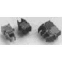
Figure 1. Comparison of Shielded Twisted Pair vs. Fiber Optic Snap-in Connector.
2
TWISTED PAIR
SHIELDED
3. Fiber Optic Connectors vs. Electrical Connectors
In the past, many design engineers were reluctant to de-
sign with fiber optics. Terminating fiber cable was more
time consuming than connecting twisted-pair wire be-
cause fibers required epoxy and their ends needed to be
polished. Large-core polymer optical fiber [POF] and the
new crimp and cleave technology for the Versatile Link
Snap-in connector (V-System) allow fiber optic cables to
be terminated more easily than shielded twisted-pair
cables, while offering an electromagnetic-compatible
communication link. This is a very strong reason for us-
ing fiber optic cables, a reason that the installation and
service divisions of a company should also accept.
4. Galvanic Insulation
Ground-loop currents due to different ground poten-
tials are a common problem in industrial communica-
tion networks. Ground loops and their associated noise
problems are totally eliminated by the insulation char-
acteristics of fiber, allowing a straightforward and fast
system integration. In addition, the insulating property
of glass and plastic fibers is ideal for many monitor and
control functions needed in high-voltage applications.
For intrinsically safe applications, which are common in
the chemical industry, fiber optics is easy to qualify and
is also the best medium for connecting one electrical de-
vice to another through an isolation barrier.
CONNECTOR
FIBER OPTIC
SNAP-IN
Related parts for HFBR-0528
Image
Part Number
Description
Manufacturer
Datasheet
Request
R

Part Number:
Description:
Fiber Optic Transmitters, Receivers, Transceivers 1300nm 155MBd 16-pin DIP ST Rx
Manufacturer:
Avago Technologies US Inc.

Part Number:
Description:
FIBER OPTIC TX 125 MBD 650N
Manufacturer:
Avago Technologies US Inc.
Datasheet:

Part Number:
Description:
Fiber Optic Evaluation Kit
Manufacturer:
Avago Technologies US Inc.
Datasheet:

Part Number:
Description:
RECEIVER FIBER OPTIC ST 266MBD
Manufacturer:
Avago Technologies US Inc.
Datasheet:

Part Number:
Description:
RCVR OPT HI SPEED VERS LINK HORZ
Manufacturer:
Avago Technologies US Inc.
Datasheet:

Part Number:
Description:
RCVR OPT HI SPEED VERS LINK VERT
Manufacturer:
Avago Technologies US Inc.
Datasheet:

Part Number:
Description:
TXRX OPTICAL 850NM VCSEL MT-RJ
Manufacturer:
Avago Technologies US Inc.
Datasheet:

Part Number:
Description:
TXRX MM SFP LC CONN BAIL DELATCH
Manufacturer:
Avago Technologies US Inc.
Datasheet:

Part Number:
Description:
TXRX MMF SFP GBE/FC BAIL DELATCH
Manufacturer:
Avago Technologies US Inc.
Datasheet:

Part Number:
Description:
XMITTER FIBER OPTIC 266MBD ST
Manufacturer:
Avago Technologies US Inc.
Datasheet:

Part Number:
Description:
OPTOCOUPLER GATE DRV 2A 16-SOIC
Manufacturer:
Avago Technologies US Inc.
Datasheet:
Part Number:
Description:
OPTOCOUPLER 2CH 2.5A 16-SOIC
Manufacturer:
Avago Technologies US Inc.
Datasheet:

Part Number:
Description:
OPTOCOUPLER GATE DRV 0.4A 16SOIC
Manufacturer:
Avago Technologies US Inc.
Datasheet:

Part Number:
Description:
OPTOCOUPLER 2.0A 250KHZ 8-DIP
Manufacturer:
Avago Technologies US Inc.
Datasheet:

Part Number:
Description:
OPTOCOUPLER 2.0A 250KHZ GW 8-SMD
Manufacturer:
Avago Technologies US Inc.
Datasheet: