HFBR-0528 Avago Technologies US Inc., HFBR-0528 Datasheet - Page 3
HFBR-0528
Manufacturer Part Number
HFBR-0528
Description
KIT EVAL FIBER OPTIC 10MBD
Manufacturer
Avago Technologies US Inc.
Datasheet
1.HFBR-0528.pdf
(16 pages)
Specifications of HFBR-0528
Main Purpose
Interface, Fiber Optics
Embedded
No
Utilized Ic / Part
HFBR-1528, HFBR-2528
Primary Attributes
10MBd, Communication up to 50m using 1mm POF
Secondary Attributes
Crimpless Connectors
Silicon Core Number
HFBR-1528, HFBR-2528
Kit Contents
TX/RX Mods, Cable, Pol Kit, SW, Pwr. Sup
Silicon Family Name
Versatile Link
Features
Fiber Optic Transmitter And Receiver
Lead Free Status / RoHS Status
Lead free / RoHS Compliant
Other names
516-2144
HFBR-0528
HFBR-0528


5510-2
II. Product Description
1. Housing and optical port
The Versatile Link family has been used successfully in
many different industrial applications based on plastic
fibers. Users have the benefit of a reliable system that is
easy to install in the field. The compact package is made
of a flame retardant (UL V-0) material in a standard, six-
pin DIP. Transmitters or receivers can be stacked togeth-
er, creating duplex optical ports that save printed circuit
board space and avoid fault connections. The conduc-
tive housing of the HFBR-2528Z receiver provides an ex-
cellent EMI shield. The color-coded packages eliminate
confusion between transmitters and receivers. A plug
protects the optical port during auto-insertion and sol-
dering.
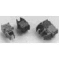
Figure 2. Package Construction.
Figure 3. Connector Alignment to Transmitter LED or Receiver IC.
The Versatile Link package uses an active alignment sys-
tem to ensure proper coupling between the fiber and
the optoelectronic converter. Figure 3 illustrates how the
alignment system operates. The precision-molded lens
on the insert is located at the bottom of a depression in
the shape of a truncated cone. The connector is inserted
into the package; the jaws of the housing force the bev-
elled end of the connector into the cone-shaped depres-
sion. This accurately centers the fiber directly above the
molded lens on the insert and ensures efficient, reliable
and repeatable connections.
3
5510-4
CONNECTOR
FIBER
INSERT
IC DIE
LENS
LEAD FRAME
Figure 4. Typical Transmitter Output Power vs. Drive Current.
2. Transmitter Technology
The new HFBR-528Z transmitter uses a high quantum
efficiency LED based on a new Avago Technologies AlIn-
GaP technology. At a 60 mA drive current, the coupled
power into a mm POF is typically -3 dBm, a 6 dB im-
provement over previously used transmitters. With a
center wavelength of 650 nm at room temperature, the
transmitter is in the minimum attenuation window of
the POF. Typical link distances of 00 m with low-cost
plastic fibers are now a reality. When using the 200 µm
HCS fiber link, 500 m distances are possible. In addition
to the higher coupled power, the optical rise and fall
times have become much faster, allowing much simpler
LED drive circuits without the need for peaking and pre-
biasing for data rates of 0 MBd.
3. Receiver Technology
The new HFBR-2528Z receiver with its TTL/CMOS-com-
patible output is specified for data rates from dc to 0
MBd NRZ (non-return to zero). It has a sensitivity of -2
dBm peak with mm POF, or a sensitivity of -23 dBm peak
with 200 HCS
low to high) and t
tributed to achieve pulse-width distortion (PWD) of less
than ±30 ns over a large input power range. As a result,
LED drive current adjustments for different link lengths
and fiber types are unnecessary.
-10
-15
-20
-25
-30
-35
-5
5
0
1
2
I
200/230 HCS
f
-TRANSMITTER DRIVE CURRENT (mA)
3
1 mm POF
®
fiber. Propagation delay times t
5
PHL
10
(output high to low) are equally dis-
20 30
50
100
PLH
(output
Related parts for HFBR-0528
Image
Part Number
Description
Manufacturer
Datasheet
Request
R

Part Number:
Description:
Fiber Optic Transmitters, Receivers, Transceivers 1300nm 155MBd 16-pin DIP ST Rx
Manufacturer:
Avago Technologies US Inc.

Part Number:
Description:
FIBER OPTIC TX 125 MBD 650N
Manufacturer:
Avago Technologies US Inc.
Datasheet:

Part Number:
Description:
Fiber Optic Evaluation Kit
Manufacturer:
Avago Technologies US Inc.
Datasheet:

Part Number:
Description:
RECEIVER FIBER OPTIC ST 266MBD
Manufacturer:
Avago Technologies US Inc.
Datasheet:

Part Number:
Description:
RCVR OPT HI SPEED VERS LINK HORZ
Manufacturer:
Avago Technologies US Inc.
Datasheet:

Part Number:
Description:
RCVR OPT HI SPEED VERS LINK VERT
Manufacturer:
Avago Technologies US Inc.
Datasheet:

Part Number:
Description:
TXRX OPTICAL 850NM VCSEL MT-RJ
Manufacturer:
Avago Technologies US Inc.
Datasheet:

Part Number:
Description:
TXRX MM SFP LC CONN BAIL DELATCH
Manufacturer:
Avago Technologies US Inc.
Datasheet:

Part Number:
Description:
TXRX MMF SFP GBE/FC BAIL DELATCH
Manufacturer:
Avago Technologies US Inc.
Datasheet:

Part Number:
Description:
XMITTER FIBER OPTIC 266MBD ST
Manufacturer:
Avago Technologies US Inc.
Datasheet:

Part Number:
Description:
OPTOCOUPLER GATE DRV 2A 16-SOIC
Manufacturer:
Avago Technologies US Inc.
Datasheet:
Part Number:
Description:
OPTOCOUPLER 2CH 2.5A 16-SOIC
Manufacturer:
Avago Technologies US Inc.
Datasheet:

Part Number:
Description:
OPTOCOUPLER GATE DRV 0.4A 16SOIC
Manufacturer:
Avago Technologies US Inc.
Datasheet:

Part Number:
Description:
OPTOCOUPLER 2.0A 250KHZ 8-DIP
Manufacturer:
Avago Technologies US Inc.
Datasheet:

Part Number:
Description:
OPTOCOUPLER 2.0A 250KHZ GW 8-SMD
Manufacturer:
Avago Technologies US Inc.
Datasheet: