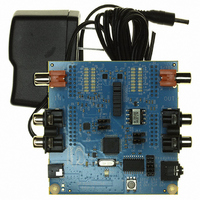
QF1DA512-DK Quickfilter Technologies LLC, QF1DA512-DK Datasheet - Page 18

QF1DA512-DK
Manufacturer Part Number
QF1DA512-DK
Description
KIT DEV FOR QF1DA512
Manufacturer
Quickfilter Technologies LLC
Series
SavFIRe™r
Datasheet
1.QF1DA512-QN-T.pdf
(42 pages)
Specifications of QF1DA512-DK
Main Purpose
Filters, Digital Filter Design
Embedded
Yes, ASIC
Utilized Ic / Part
QF1Da512
Primary Attributes
1 512 Tap FIR Filter, 12 ~ 24 Bit
Secondary Attributes
Quickfilter Software Design Tool GUI, Works from 10 ~ 500ksps ADC Data Rates
For Use With
WM2582 - EVALDI EARBUDS TYPE Y686-1006 - BOARD MSP-MOJO + EXPANSION HEADR
Lead Free Status / RoHS Status
Lead free / RoHS Compliant
Other names
686-1010
In standard mode for data sampling at a 48 kHz rate, the latency will result in:
In duplication mode for data sampling at a 48 kHz rate, the latency will result in:
Note: If using the Quickfilter Pro development software the latency of a particular filter is calculated and displayed in the Information bar
10 Digital Gain and Compression (DGC)
For standard FIR pass-band/stop-band filters, DGC is not necessary as the pass-band is designed for 0dB (unity). The Quickfilter Pro™
Freehand filter editor supports an audio mode where the gain and compression variables are automatically determined for the user.
Optionally, Quickfilter Pro™ provides direct access to and guidance for all the DGC parameters.
Mode of Operation
When Compression is enabled, Gain is applied to the FIR output signal when the input signal is below a Threshold value. Above the
Threshold value, Gain and Compression are applied to the FIR output signal. When the Compressor is bypassed (THRES = FFh), only
Gain is applied to the FIR output signal. The default value for Gain is 1.
Both Gain and Compression (ratio) are comprised of 4 integer bits and 12 factional bits.
The DGC parameters are,
properly set these parameters. Also, care must be taken to avoid clipping when using the DGC function. Additional guidance can be
found in section 14.
11 CONTROL REGISTERS
Overview
The QF1Da512 internal data is separated into configuration registers and coefficient memory.
Rev A8 January 7, 2009
Note – not all combinations of DGC parameters yield valid compression values settings. Therefore, it is best to use Quickfilter Pro™ to
1.
2.
3.
4.
on the “Filter” tab.
Duplication mode is comprised of two serial QF1Da512s of which the first device is in duplication mode and the second device is
in standard mode.
Two 512 tap (maximum) filters in series:
Device Configuration
Threshold – signal levels above this value are compressed
Gain – the amount of gain to apply to the FIR output signal below the Threshold
Ratio – the inverse slope of the compression curve above the Threshold
Maximum – Maximum input amplitude value
FIR Coefficients
Registers
512 tap (maximum) filter:
Two 100 tap filters in series:
100 tap filter:
Address Range
0x0000 – 0x0021
0x0000 – 0x00FF
Table 2
PRELIMINARY DATA SHEET
Latency = 5.49ms
Latency = 1.20ms
Latency = 5.57ms
Latency = 1.28ms
Register and Memory Format
18
Data Size
32 bit
8 bit
Write OpCode
0x82
0x86
Gain
Gain
Read Opcode
www.quickfiltertech.com
0x83
0x87
1/Ratio
1/Ratio
QF1Da512


