STEVAL-IHM010V1 STMicroelectronics, STEVAL-IHM010V1 Datasheet
STEVAL-IHM010V1
Specifications of STEVAL-IHM010V1


Related parts for STEVAL-IHM010V1


STEVAL-IHM010V1 Summary of contents
Page 1
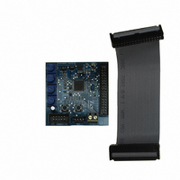
... IGBT Power module evaluation kit - ST7MC control board Introduction The ST7MC evaluation board STEVAL-IHM010V1 is a complete development platform for STMicroelectronics' ST7MC microcontroller. Based on a cost effective, flexible and open design, it allows easy demonstration of ST7MC capabilities and enables rapid evaluation of the MTC microcontroller's peripherals. It includes the ST7MC 8-bit microcontroller with 16 K internal Flash memory ...
Page 2
Contents Contents 1 System architecture . . . . . . . . . . . . . . . . . . . . . . . . . . . . . . . . . . . ...
Page 3
UM0430 7.4.8 7.4.9 7.4.10 7.4.11 7.4.12 7.4.13 7.4.14 7.4.15 7.5 Driving the AC induction motor . . . . . . . . . . . . . . . . . . . . . . . . . ...
Page 4
Contents 7.8.5 7.8.6 7.8.7 8 Bill of materials . . . . . . . . . . . . . . . . . . . . . . . . . . . . . . . . ...
Page 5
UM0430 List of tables Table 1. ST7FMC2S4T6 Functions . . . . . . . . . . . . . . . . . . . . . . . . . . . . . . . . ...
Page 6
... List of figures List of figures Figure 1. STEVAL-IHM010V1 . . . . . . . . . . . . . . . . . . . . . . . . . . . . . . . . . . . . . . . . . . . . . . . . . . . . . . . 1 Figure 2. Motor control system architecture Figure 3. Control board architecture . . . . . . . . . . . . . . . . . . . . . . . . . . . . . . . . . . . . . . . . . . . . . . . . . 12 Figure 4. Control board layout . . . . . . . . . . . . . . . . . . . . . . . . . . . . . . . . . . . . . . . . . . . . . . . . . . . . . . 13 Figure 5. MC Connector pin out . . . . . . . . . . . . . . . . . . . . . . . . . . . . . . . . . . . . . . . . . . . . . . . . . . . . . 14 Figure 6. ICC connector . . . . . . . . . . . . . . . . . . . . . . . . . . . . . . . . . . . . . . . . . . . . . . . . . . . . . . . . . . . 15 Figure 7. SDI connector . . . . . . . . . . . . . . . . . . . . . . . . . . . . . . . . . . . . . . . . . . . . . . . . . . . . . . . . . . . 16 Figure 8. Control board schematic . . . . . . . . . . . . . . . . . . . . . . . . . . . . . . . . . . . . . . . . . . . . . . . . . . . 17 Figure 9. STVD7 for InDART-STX Toolset configuration Figure 10. ...
Page 7
... STEVAL-IHM010V1, one power board STEVAL-IHM011V1, one motor and the power supply. The control board STEVAL-IHM010V1 is a microcontroller (ST7MC) based board that provides the driving signals related to the motor selected and the driving strategies. Driving signals are constituted of 6 PWM signals in the range of 0-5V paired in high side/low side pairs of one pair for each leg ...
Page 8
Safety and operating instructions 2 Safety and operating instructions 2.1 General During assembly and operation, the IGBT power module eval kit poses several inherent hazards, including bare wires, moving or rotating parts, and hot surfaces. There is danger of serious ...
Page 9
UM0430 Warning: 3 ST7FMC2S4T6 Microcontroller functions 3.1 Main features ● TQFP44 package ● dual voltage FLASH program memory with read-out protection capability ● 768 bytes RAM (256 Stack bytes) ● Clock, Reset And Supply Management with: – enhanced ...
Page 10
ST7FMC2S4T6 Microcontroller functions Table 1. ST7FMC2S4T6 Functions Function I/O name MCO0 to MCO5 MCIA, MCIB, MCIC MCV NMCES OAP OAN MTC OAZ MCC MCPWMU MCPWMV MCPWMW MCZEM MCDEM MISO SPI MOSI SCK RDI LINSCI™ TDO AIN0 AIN1 10-bit ADC AIN13 ...
Page 11
... Bias current (typical) MC PWM Output current (source) MC PWM Output current (sink) MC BEMF Input (sink) GP I/O Pin (source) GP I/O Pin (sink) HS I/O Pin (source) Control board electrical characteristics Table 2 may cause permanent damage to the device. This STEVAL-IHM010V1 Min 4.5 4.5 4.5 10 Unit Max 5 ...
Page 12
... Board architecture 5 Board architecture The STEVAL-IHM010V1 can be schematized as in Figure 3. Control board architecture The heart of the control board is the ST7MC microcontroller which is provided with a dedicated peripheral to drive the three-phase brushless motor. The user interface is constituted of four potentiometers (P1, P2, P3, P4) which are used to ...
Page 13
UM0430 Two communication systems can be established with the microcontroller: – ICC Used for programming/debugging purposes – SCI Used for data exchange through SDI connector The control board is connected to the power board through a specific connector (MC Connector). ...
Page 14
Board architecture Figure 5. MC Connector pin out Table 3. Motor control connector Pin 14/48 Description Emergency stop Ground High side PWM ...
Page 15
UM0430 Table 3. Motor control connector (continued) Pin 5.2 ICC connector The ICC Connector is used to establish ICC communication for programming/debugging ...
Page 16
Board architecture 5.3 Serial Data Interface (SDI) The board is provided with a serial data interface (SDI) able to establish SCI communication with an external device. We suggest using an isolation board between the SDI and the external devices. The ...
Page 17
UM0430 6 Board schematics Figure 8. Control board schematic Board schematics 17/48 ...
Page 18
Motor control demonstration 7 Motor control demonstration 7.1 Environmental considerations Warning: The kit is not electrically isolated from the AC input. This topology is very common in AC drives. The microprocessor is grounded by the integrated Ground of the DC ...
Page 19
... UM0430 7.2 Hardware requirements To set up the IGBT power module eval kit system the following items are required: ● The control board: STEVAL-IHM010V1 ● The power board: STEVAL-IHM011V1 ● 34-pin flat cable ● High voltage isolated AC power supply up to 220 ● Isolated DC power supply ● ...
Page 20
Motor control demonstration During the first run of the software after installation, a prompt for the configuration of the toolset should appear. The toolset can be configured at any time by opening the "tools options" inside stvd7 this, ...
Page 21
UM0430 Table 4. Firmware libraries arranged according to driving strategy Firmware name AC_3PH_SR BLAC_3PH_SR BLDC_3PH_SL BLDC_3PH_SR Note: We suggest making a backup copy of the original working folder for each firmware. The following procedure modifies the original content of the ...
Page 22
Motor control demonstration For a detailed description of the configuration files and how to manually customize the related parameters, see AN1904, AN1905, AN1947. 7.4.3 Motor type selection After "IGBT PM EV KIT - GUI" is started, the motor type choice ...
Page 23
UM0430 7.4.4 "3 Phase BLAC/DC (trapezoidal)" settings Figure 11. "3 Phase BLAC/DC (trapezoidal)" basic parameters window Table 6. "3 Phase BLAC/DC (trapezoidal)" basic parameters Parameter name Poles pairs the manner in which to run the motor, either open loop (without ...
Page 24
Motor control demonstration Table 6. "3 Phase BLAC/DC (trapezoidal)" basic parameters (continued) Parameter name Duty cycle the value of current flowing inside one (of three) phases of the motor at the end of the Current reference Number of Z events ...
Page 25
UM0430 7.4.5 "3 Phase BLAC/DC (trapezoidal)" advanced settings Clicking the "advanced settings" button (see dialog box (see Figure motor type parameters are set. Figure 12. “3 Phase BLAC/DC (trapezoidal)" advanced parameters window Table 7. "3 Phase BLAC/DC (trapezoidal)" advanced parameters ...
Page 26
Motor control demonstration Table 7. "3 Phase BLAC/DC (trapezoidal)" advanced parameters (continued) Parameter name After D blanking window Z event counter filter Threshold voltage After C blanking window D event counter filter Demagnetization method Demagnetization time Force duty cycle during ...
Page 27
UM0430 Table 8. “3 Phase AC induction motor (sinewave)” basic parameters Parameter name Poles pairs Speed regulation Speed sensor tacho (pulse x rev) Minimum Maximum Min voltage Low frequency High frequency Voltage slew rate Start-Up stator frequency Max duration Min ...
Page 28
Motor control demonstration 7.4.7 "3 Phase AC induction motor (sinewave)" advanced settings Clicking the "advanced settings" button (see dialog box (see Figure (sinewave)" motor type parameters are set. Figure 14. "3 Phase AC induction motor (sinewave)" advanced parameters window Table ...
Page 29
UM0430 7.4.8 "3 Phase PMAC motor (sinewave)" settings Figure 15. "3 Phase PMAC motor (sinewave)" basic parameters window Table 10. "3 Phase PMAC motor (sinewave)" basic parameters Parameter name Poles pairs Speed regulation Sensor configuration Min Max Min voltage Low ...
Page 30
Motor control demonstration Table 10. "3 Phase PMAC motor (sinewave)" basic parameters (continued) Parameter name Voltage slew rate Start-up stator frequency Max duration Min rotor frequency to validate closed loop Integral coefficient (Ki) Proportional coefficient (Kp) Sampling time Set phase ...
Page 31
UM0430 Figure 16. "3 Phase PMAC motor (sinewave)" advanced parameters window Table 11. "3 Phase PMAC motor (sinewave)" advanced parameters Params name Switches PWM frequency Dead times value selects from available preset dead time duration values in microseconds (µs) Software ...
Page 32
Motor control demonstration 7.4.10 Changing the maximum current allowed by GUI The maximum current allowed by GUI has been set to 4.1 amps. This value may be changed by modifying the file "gui.ini" inside the folder where the file "IGBT ...
Page 33
UM0430 7.4.12 Programming the firmware Before programming the firmware, the control board must be supplied and connected to the PC using the inDART board. We suggest setting up the system as in Figure 18. System setup for programming phase 1. ...
Page 34
Motor control demonstration Once the ST7VD for inDART has been installed, the "datablaze programmer" utility that can be used to program the firmware using the inDART-STX can also be installed. 4. Run the Softec datablaze programmer utility. 5. Click the ...
Page 35
UM0430 Figure 20. Programming option auto window 12. Press start to program the device error window appears, make sure that the inDART-STX board is connected to the ControlBDST7MC2 control board and that the control board is well supplied. ...
Page 36
... Specific connection (sensor) To drive the motor also in closed loop mode, the motor must include a Tachometer speed sensor. For this demonstration we suggest using one AC Induction Selni Motor. Connect the two sensor signal wires to the J2 connector of the power board STEVAL- IHM011V1 in any order. 36/48 demonstration) (see power board user manual) ...
Page 37
UM0430 7.5.2 Specific jumper settings To set up the power board jumper, follow the instructions in the power board user manual. Open the J5 jumper on the control board. Keep J2 of the control board open. 7.5.3 LED behavior after ...
Page 38
... Driving the BLDC Motor (trapezoidal - sensorless) 9 Before proceeding with the motor control demonstration, the power board STEVAL- IHM011V1 must be set up to drive "3 Phase BLAC/DC (trapezoidal - sensorless)" settings as described in the power board user manual. 10 Let's start the demonstration driving the brushless permanent magnet motor in voltage mode - open loop - sensorless ...
Page 39
UM0430 7.6.3 LED behavior after power on Turn on the power supply. For this demonstration the power supply output voltage should be set to 30 Vdc and current limitation of the power supply should be set to 4 amp. After ...
Page 40
... Driving the BLDC Motor (trapezoidal - sensored) 13 Before proceeding with the motor control demonstration, the power board STEVAL- IHM011V1 must be set up to drive "3 Phase BLAC/DC (trapezoidal - sensored)" settings as described in the power board user manual. 14 Let's start the demonstration driving the brushless permanent magnet motor in voltage mode - open loop - sensor 60° ...
Page 41
UM0430 set up for voltage mode - open loop - sensor 60° driving (see BLAC/DC (trapezoidal)" 7.7.1 Specific connection (sensor) To drive the motor, the motor must have three position sensors, in this case three hall sensors. For this demonstration ...
Page 42
Motor control demonstration During any state: idle, start, run or brake, if the red LED stays on along with the brake of the motor, this indicates a fault condition. A fault condition is due to one of the following conditions: ...
Page 43
... Driving the BLAC motor 17 Before proceeding with the motor control demonstration, the power board STEVAL- IHM011V1 must be set up to drive "3 phase PMAC (sinusoidal - sensored)" settings as described in the power board user manual. 18 Let's start the demonstration driving the brushless permanent magnet motor in open loop. ...
Page 44
Motor control demonstration 7.8.3 LED behavior after power on Turn on the power supply. For this demonstration the power supply output voltage should be set to 30 Vdc and current limitation of the power supply should be set to 4 ...
Page 45
UM0430 Table 18. Potentiometer functionality based on open/closed loop driving strategy (continued) Open loop manual setting of the phase shift; the maximum P3 CCW position is 0° of phase shift and the maximum CW position is 360° of phase shift ...
Page 46
Bill of materials 8 Bill of materials Table 19. Bill of materials Item Qty ...
Page 47
... UM0430 9 References This user manual provides information about using your STEVAL-IHM010V1 and its hardware features. For additional information about supporting software and tools, please refer to: ST7MC Datasheet. Complete information about microcontroller features and peripherals. ST7MC Motor Control related application notes. Complete information about motor control libraries developed for ST7MC microcontroller ...
Page 48
... Information in this document is provided solely in connection with ST products. STMicroelectronics NV and its subsidiaries (“ST”) reserve the right to make changes, corrections, modifications or improvements, to this document, and the products and services described herein at any time, without notice. All ST products are sold pursuant to ST’s terms and conditions of sale. ...