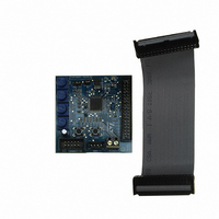
STEVAL-IHM010V1 STMicroelectronics, STEVAL-IHM010V1 Datasheet - Page 12

STEVAL-IHM010V1
Manufacturer Part Number
STEVAL-IHM010V1
Description
KIT IGBT PWR MODULE CTRL ST7MC
Manufacturer
STMicroelectronics
Type
Motor / Motion Controllers & Driversr
Specifications of STEVAL-IHM010V1
Main Purpose
Power Management, Motor Control
Embedded
Yes, MCU, 8-Bit
Utilized Ic / Part
ST7FMC2S4
Primary Attributes
3-Ph Brushless BLDC, AC & 3-Ph AC Induction (ACIM) Motors
Secondary Attributes
Graphic User Interface, 4 Pots for Runtime Settings, Start/Stop and Reset Buttons
Input Voltage
5 V
Product
Power Management Modules
Silicon Manufacturer
ST Micro
Core Architecture
ARM
Core Sub-architecture
ARM7TDMI
Silicon Core Number
ST7
Silicon Family Name
ST7MCx
Kit Contents
Board
Lead Free Status / RoHS Status
Lead free / RoHS Compliant
For Use With/related Products
ST7MC
Other names
497-8400
Board architecture
5
12/48
Board architecture
The STEVAL-IHM010V1 can be schematized as in
Figure 3.
The heart of the control board is the ST7MC microcontroller which is provided with a
dedicated peripheral to drive the three-phase brushless motor.
The user interface is constituted of four potentiometers (P1, P2, P3, P4) which are used to
set parameters related to the specific drive, see
Two push buttons are also present:
●
●
Two LEDs (green and red) provide information about the status of the system. Their
behavior is related to the specific drive, see
In normal functionality it is expected that the board is supplied by the MC connector, but for
stand-alone operation, an auxiliary supply connector for 5 V power supply is included on the
board. Providing more than 5.5 V through this connector may cause permanent damage to
the device since no over voltage protection device is present.
The board is supplied with 2 Kbit EEPROM (M95020) connected to the micro by an SPI bus.
To enable the onboard EEPROM memory, the jumper J2 must be closed and the debug
feature must be disabled inside the firmware.
J5 can be set by the user by connecting a jumper between pins 1-2 or 2-3. This setting is
related to a specific drive, see
Reset button for a "hardware reset" of the board.
Start/stop button used to start and stop motor driving, see
demonstration.
Control board architecture
Section 7: Motor control
Section 7: Motor control
Section 7: Motor control
Figure
demonstration.
3.
Section 7: Motor control
demonstration.
demonstration.
UM0430


