MCP3424EV Microchip Technology, MCP3424EV Datasheet - Page 16
MCP3424EV
Manufacturer Part Number
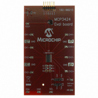
MCP3424EV
Description
EVALUATION BOARD FOR MCP3424
Manufacturer
Microchip Technology
Specifications of MCP3424EV
Number Of Adc's
1
Number Of Bits
18
Sampling Rate (per Second)
3.75 ~ 240
Data Interface
I²C
Inputs Per Adc
4 Differential
Input Range
±2.048 V
Power (typ) @ Conditions
135µA @ 240sps
Voltage Supply Source
Single Supply
Operating Temperature
-55°C ~ 125°C
Utilized Ic / Part
MCP3424
Processor To Be Evaluated
MCP3424
Lead Free Status / RoHS Status
Lead free / RoHS Compliant
Lead Free Status / RoHS Status
Lead free / RoHS Compliant, Lead free / RoHS Compliant
Available stocks
Company
Part Number
Manufacturer
Quantity
Price
Company:

Part Number:
MCP3424EV
Manufacturer:
Microchip Technology
Quantity:
135


MCP3424
If the configuration byte is read repeatedly by clocking
continuously after reading the data bytes (i.e., after the
5th byte in the 18-bit conversion mode), the state of the
RDY bit indicates whether the device is ready with new
conversion result. When the Master finds the RDY bit is
cleared, it can send a stop bit to exit the current read
operation and send a new read command for the latest
conversion data. Once the conversion data has been
read, the ready bit toggles to ‘1’ until the next new
conversion data is ready. The conversion data in the
output register is overwritten every time a new conver-
sion is completed.
Figure 5-4
reading the conversion data. The user can rewrite the
configuration byte any time for a new setting.
and
bit operation.
TABLE 5-1:
TABLE 5-2:
DS22088A-page 16
R/W O/C RDY
R/W O/C RDY
0
0
0
0
1
1
1
1
Table 5-2
0
0
1
1
0
0
1
1
and
show the examples of the configuration
0
1
0
1
0
1
0
1
Figure 5-5
WRITE CONFIGURATION BITS
READ CONFIGURATION BITS
No effect if all other bits remain
the same - operation continues
with the previous settings
Initiate One-Shot Conversion
Initiate Continuous Conversion
Initiate Continuous Conversion
New conversion result in
One-Shot conversion mode has
just been read. The RDY bit
remains low until set by a new
write command.
One-Shot Conversion is in
progress. The conversion result
is not updated yet. The RDY bit
stays high until the current
conversion is completed.
New conversion result in Contin-
uous Conversion mode has just
been read. The RDY bit changes
to high after reading the conver-
sion data.
The conversion result in Continu-
ous Conversion mode was
already read. The next new con-
version data is not ready. The
RDY bit stays high until a new
conversion is completed.
show the examples of
Operation
Operation
Table 5-1
5.3
The MCP3424 device communicates with Master
(microcontroller) through a serial I
Circuit)
(100 kbits/sec), fast (400 kbits/sec) and high-speed
(3.4 Mbits/sec) modes. The serial I
2-wire data bus communication protocol using
open-drain SCL and SDA lines.
The MCP3424 can only be addressed as a slave. Once
addressed, it can receive configuration bits or transmit
the latest conversion results. The serial clock pin (SCL)
is an input only and the serial data pin (SDA) is
bidirectional. An example of a hardware connection
diagram is shown in
More details of the I
in Section 5.6 “I
5.3.1
The Master starts communication by sending a START
bit and terminates the communication by sending a
STOP bit. The first byte after the START bit is always
the address byte of the device, which includes the
device code, address bits, and R/W bit. The device
code for the MCP3424 device is 1101, which is
programmed at the factory. The I
A1, A0) are user programmable and determined by the
logic status of the two external address selection pins
on the user’s application board (Adr0 and Adr1 pins).
The Master must know the Adr0 and Adr1 pin
conditions before sending read or write command.
Figure 5-1
byte.
The three address bits allow up to eight MCP3424
devices on the same data bus line. The (R/W) bit
determines if the Master device wants to read the
conversion data or write to the Configuration register. If
the (R/W) bit is set (read mode), the MCP3424 outputs
the conversion data in the following clocks. If the (R/W)
bit is cleared (write mode), the MCP3424 expects a
configuration byte in the following clocks. When the
MCP3424 receives the correct address byte, it outputs
an acknowledge bit after the R/W bit.
Figure 5-1
Figure 5-3
configuration register bits and read the conversion
results.
I
2
C Serial Communications
shows the details of the MCP3424 address
through
interface
I
2
shows the MCP3424 address byte.
C DEVICE ADDRESSING
2
C Bus Characteristics”.
Figure 5-5
2
Figure
C bus characteristic is described
© 2008 Microchip Technology Inc.
and
6-1.
show how to write the
supports
2
2
C address bits (A2,
2
C (Inter-Integrated
C is a bidirectional
standard
Related parts for MCP3424EV
Image
Part Number
Description
Manufacturer
Datasheet
Request
R

Part Number:
Description:
Manufacturer:
Microchip Technology Inc.
Datasheet:
Part Number:
Description:
Manufacturer:
Microchip Technology Inc.
Datasheet:
Part Number:
Description:
Manufacturer:
Microchip Technology Inc.
Datasheet:
Part Number:
Description:
Manufacturer:
Microchip Technology Inc.
Datasheet:
Part Number:
Description:
Manufacturer:
Microchip Technology Inc.
Datasheet:
Part Number:
Description:
Manufacturer:
Microchip Technology Inc.
Datasheet:
Part Number:
Description:
Manufacturer:
Microchip Technology Inc.
Datasheet:
Part Number:
Description:
Manufacturer:
Microchip Technology Inc.
Datasheet: