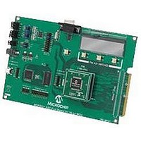
MCP3901EV-MCU16 Microchip Technology, MCP3901EV-MCU16 Datasheet - Page 28

MCP3901EV-MCU16
Manufacturer Part Number
MCP3901EV-MCU16
Description
BOARD EVAL FOR 2CH ADC MCP3901
Manufacturer
Microchip Technology
Datasheets
1.MCP3901A0-ISS.pdf
(60 pages)
2.MCP3901A0-ISS.pdf
(30 pages)
3.MCP3901EV-MCU16.pdf
(38 pages)
4.MCP3901EV-MCU16.pdf
(38 pages)
Specifications of MCP3901EV-MCU16
Number Of Adc's
2
Number Of Bits
24
Data Interface
SPI™
Inputs Per Adc
1 Differential
Input Range
±1 V
Voltage Supply Source
Analog and Digital
Operating Temperature
-40°C ~ 85°C
Utilized Ic / Part
MCP3901
Silicon Manufacturer
Microchip
Application Sub Type
ADC
Kit Application Type
Data Converter
Silicon Core Number
MCP3901, PIC24F, PIC24H, DsPIC33, PIC18F86J55
Kit Contents
Board
Lead Free Status / RoHS Status
Lead free / RoHS Compliant
MCP3901
5.6
The second-order modulator, SINC
and analog input structure all work together to produce
the device transfer function for the Analog-to-Digital
conversion (see
The channel data is either a 16-bit or 24-bit word,
presented in a 23-bit or 15-bit plus sign, two’s
complement format, and is MSB (left) justified.
The ADC data is two or three bytes wide depending on
the WIDTH bit of the associated channel. The 16-bit
mode includes a round to the closest 16-bit word
(instead of truncation) in order to improve the accuracy
of the ADC data.
EQUATION 5-3:
5.6.1
The ADC resolution is a function of the OSR
(Section 5.5 “SINC3
same for both channels. No matter what the resolution
is, the ADC output data is always presented in 24-bit
words, with added zeros at the end if the OSR is not
large enough to produce 24-bit resolution (left
justification).
TABLE 5-4:
TABLE 5-5:
DS22192C-page 28
0 1 1 1
0 1 1 1
0 0 0 0
1 1 1 1
1 0 0 0
1 0 0 0
0 1 1 1
0 1 1 1
0 0 0 0
1 1 1 1
1 0 0 0
1 0 0 0
DATA_CHn
DATA_CHn
ADC Output Coding
ADC RESOLUTION AS A FUNCTION
OF OSR
1 1 1 1
1 1 1 1
0 0 0 0
1 1 1 1
0 0 0 0
0 0 0 0
1 1 1 1
1 1 1 1
0 0 0 0
1 1 1 1
0 0 0 0
0 0 0 0
Equation
OSR = 256 OUTPUT CODE EXAMPLES
OSR = 128 OUTPUT CODE EXAMPLES
ADC Output Code (MSB First)
ADC Output Code (MSB First)
Filter”). The resolution is the
=
=
5-3).
1 1 1 1
1 1 1 1
0 0 0 0
1 1 1 1
0 0 0 0
0 0 0 0
1 1 1 1
1 1 1 1
0 0 0 0
1 1 1 1
0 0 0 0
0 0 0 0
⎛
⎝
⎛
⎝
(
------------------------------------ -
(
------------------------------------ -
V
V
CH
CH
REF+
REF+
n+
3
n+
filter, PGA, V
–
–
–
–
1 1 1 1
1 1 1 0
0 0 0 0
1 1 1 1
0 0 0 0
0 0 0 0
1 1 1 1
1 1 1 1
0 0 0 0
1 1 1 1
0 0 0 0
0 0 0 0
CH
V
CH
V
REF-
REF-
n-
n-
)
)
⎞
⎠
⎞
⎠
×
REF
×
1 1 1 1
1 1 1 1
0 0 0 0
1 1 1 1
0 0 0 0
0 0 0 0
32 768
1 1 1 1
1 1 1 1
0 0 0 0
1 1 1 1
0 0 0 0
0 0 0 0
8,388,608
,
×
In case of positive saturation (CHn+ – CHn- > V
the output is locked to 7FFFFF for 24-bit mode (7FFF
for 16-bit mode). In case of negative saturation
(CHn+ – CHn- < -V
800000 for 24-bit mode (8000 for 16-bit mode).
Equation 5-3
this transfer function needs to be multiplied by the
transfer function of the SINC
and
G 3
1 1 1 0
1 1 0 0
0 0 0 0
1 1 1 0
0 0 1 0
0 0 0 0
×
1 1 1 1
1 1 1 0
0 0 0 0
1 1 1 1
0 0 0 1
0 0 0 0
Equation
×
G 3
×
is only true for DC inputs. For AC inputs,
(For 16-Bit Mode or WIDTH = 0)
5-2).
Hexadecimal
(For 24-Bit Mode or WIDTH = 1)
Hexadecimal
0x7FFFFE
0x7FFFFC
0xFFFFFE
0x800002
0x800000
0x000000
0x7FFFFE
0xFFFFFF
0x7FFFFF
0x800001
0x800000
0x000000
REF
/3), the output code is locked to
© 2010 Microchip Technology Inc.
3
filter (see
23-Bit Resolution
+ 4,194,303
+ 4,194,302
- 4,194,303
- 4,194,304
+ 8,388,607
+ 8,388,606
- 8,388,607
- 8,388,608
Decimal
Decimal
-1
Equation 5-1
-1
0
0
REF
/3),


