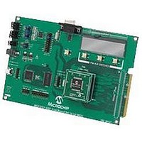
MCP3901EV-MCU16 Microchip Technology, MCP3901EV-MCU16 Datasheet - Page 45

MCP3901EV-MCU16
Manufacturer Part Number
MCP3901EV-MCU16
Description
BOARD EVAL FOR 2CH ADC MCP3901
Manufacturer
Microchip Technology
Datasheets
1.MCP3901A0-ISS.pdf
(60 pages)
2.MCP3901A0-ISS.pdf
(30 pages)
3.MCP3901EV-MCU16.pdf
(38 pages)
4.MCP3901EV-MCU16.pdf
(38 pages)
Specifications of MCP3901EV-MCU16
Number Of Adc's
2
Number Of Bits
24
Data Interface
SPI™
Inputs Per Adc
1 Differential
Input Range
±1 V
Voltage Supply Source
Analog and Digital
Operating Temperature
-40°C ~ 85°C
Utilized Ic / Part
MCP3901
Silicon Manufacturer
Microchip
Application Sub Type
ADC
Kit Application Type
Data Converter
Silicon Core Number
MCP3901, PIC24F, PIC24H, DsPIC33, PIC18F86J55
Kit Contents
Board
Lead Free Status / RoHS Status
Lead free / RoHS Compliant
7.4
This registers contains the settings for the PGA gains
for each channel as well as the BOOST options for
each channel.
REGISTER 7-4:
© 2010 Microchip Technology Inc.
bit 7
Legend:
R = Readable bit
-n = Value at POR
bit 7-5
bit 4-3
bit 2-0
PGA_CH1
R/W-0
<2>
Gain Configuration Register
PGA_CH1<2:0>: PGA Setting for Channel 1 bits
111 = Reserved (Gain = 1)
110 = Reserved (Gain = 1)
101 = Gain is 32
100 = Gain is 16
011 = Gain is 8
010 = Gain is 4
001 = Gain is 2
000 = Gain is 1
BOOST_CH<1:0> Current Scaling for High-Speed Operation bits
11 = Both channels have current x 2
10 = Channel 1 has current x 2
01 = Channel 0 has current x 2
00 = Neither channel has current x 2
PGA_CH0<2:0>: PGA Setting for Channel 0 bits
111 = Reserved (Gain = 1)
110 = Reserved (Gain = 1)
101 = Gain is 32
100 = Gain is 16
011 = Gain is 8
010 = Gain is 4
001 = Gain is 2
000 = Gain is 1
PGA_CH1
R/W-0
<1>
GAIN CONFIGURATION REGISTER (GAIN): ADDRESS 0x08
W = Writable bit
‘1’ = Bit is set
PGA_CH1
R/W-0
<0>
BOOST_
R/W-0
CH1
U = Unimplemented bit, read as ‘0’
‘0’ = Bit is cleared
BOOST_
R/W-0
CH0
PGA_CH0
R/W-0
<2>
x = Bit is unknown
PGA_CH0
R/W-0
MCP3901
<1>
DS22192C-page 45
PGA_CH0
R/W-0
<0>
bit 0


