CRD4525-Q1 Cirrus Logic Inc, CRD4525-Q1 Datasheet - Page 10
CRD4525-Q1
Manufacturer Part Number
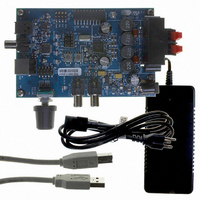
CRD4525-Q1
Description
REFERENCE BOARD FOR CS4525 PWM
Manufacturer
Cirrus Logic Inc
Series
Popguard®r
Specifications of CRD4525-Q1
Amplifier Type
Class D
Output Type
2-Channel (Stereo)
Max Output Power X Channels @ Load
15W x 2 @ 8 Ohm
Voltage - Supply
12 V ~ 18 V
Operating Temperature
0°C ~ 70°C
Board Type
Fully Populated
Utilized Ic / Part
CS4525
Lead Free Status / RoHS Status
Contains lead / RoHS non-compliant
Other names
598-1586


10
2. PIN DESCRIPTIONS - HARDWARE MODE
CLK_FREQ0
CLK_FREQ1
ADC/SP
LRCK
SCLK
SDIN
MUTE
RST
Pin Name
CLK_FREQ0
CLK_FREQ1
VD_REG
Pin #
ADC/SP
DGND
1
2
3
4
5
6
7
8
MUTE
LRCK
SCLK
SDIN
RST
LVD
VD
Clock Frequency (Input) - Determines the frequency of the clock expected to be driven into the
SYS_CLK pin. CLK_FREQ1 must be connected to DGND.
ADC/Serial Port (Input) - Selects between the Analog to Digital Converter and the Serial Port for
audio input. Selects the ADC when high or the serial port when low.
Left Right Clock (Input) - Determines which channel, Left or Right, is currently active on the serial
audio data line.
Serial Clock (Input) - Serial bit clock for the serial audio interface.
Serial Audio Data Input (Input) - Input for two’s complement serial audio data.
Mute (Input) - The PWM outputs will output silence as a 50% duty cycle signal when this pin is
driven low.
Reset (Input) - The device enters a low power mode and all internal registers are reset to their
default settings when this pin is driven low.
10
11
12
1
2
3
4
5
6
7
8
9
48
13
47
14
15
46
45
16
Top-Down (Through Package) View
44
17
Thermal Pad
48-Pin QFN Package
43
18
42
19
Pin Description
41
20
40
21
39
22
38
23
37
24
35
33
31
30
28
26
25
36
34
32
29
27
VP
OUT1
PGND
PGND
OUT2
VP
VP
OUT3
PGND
PGND
OUT4
VP
CS4525
DS726PP3
Related parts for CRD4525-Q1
Image
Part Number
Description
Manufacturer
Datasheet
Request
R

Part Number:
Description:
Development Kit
Manufacturer:
Cirrus Logic Inc
Datasheet:
Part Number:
Description:
Development Kit
Manufacturer:
Cirrus Logic Inc
Datasheet:


Part Number:
Description:
High-efficiency PFC + Fluorescent Lamp Driver Reference Design
Manufacturer:
Cirrus Logic Inc
Datasheet:
Part Number:
Description:
Development Kit
Manufacturer:
Cirrus Logic Inc
Datasheet:
Part Number:
Description:
Development Kit
Manufacturer:
Cirrus Logic Inc
Datasheet:

Part Number:
Description:
Development Kit
Manufacturer:
Cirrus Logic Inc
Datasheet:
Part Number:
Description:
Development Kit
Manufacturer:
Cirrus Logic Inc
Datasheet:
Part Number:
Description:
Development Kit
Manufacturer:
Cirrus Logic Inc
Datasheet:
Part Number:
Description:
Audio Modules & Development Tools EvalBd 30W Qd Hlf- Brdg Dig Amp Pwr Stg
Manufacturer:
Cirrus Logic Inc
Datasheet:

Part Number:
Description:
EVALUATION BOARD FOR CS8427
Manufacturer:
Cirrus Logic Inc
Datasheet:

Part Number:
Description:
BOARD EVAL FOR CS8416 RCVR
Manufacturer:
Cirrus Logic Inc
Datasheet:

Part Number:
Description:
EVALUATION BOARD FOR CS8420
Manufacturer:
Cirrus Logic Inc
Datasheet:

Part Number:
Description:
KIT DEVELOPMENT EP9315 ARM9
Manufacturer:
Cirrus Logic Inc
Datasheet: