CRD4525-Q1 Cirrus Logic Inc, CRD4525-Q1 Datasheet - Page 60
CRD4525-Q1
Manufacturer Part Number
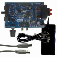
CRD4525-Q1
Description
REFERENCE BOARD FOR CS4525 PWM
Manufacturer
Cirrus Logic Inc
Series
Popguard®r
Specifications of CRD4525-Q1
Amplifier Type
Class D
Output Type
2-Channel (Stereo)
Max Output Power X Channels @ Load
15W x 2 @ 8 Ohm
Voltage - Supply
12 V ~ 18 V
Operating Temperature
0°C ~ 70°C
Board Type
Fully Populated
Utilized Ic / Part
CS4525
Lead Free Status / RoHS Status
Contains lead / RoHS non-compliant
Other names
598-1586


60
6.4.2
Full-Bridge Output Filter (Stereo or Parallel)
Figure 27
sient voltage suppression circuits are implemented as a RC snubber networks comprised of resistors R
(5.6 Ω, 1/8 W) and capacitors C
sponding output pin. These circuits decrease the slew rate of the output signal and reduce high frequency
ringing which can lead to increased EMI. The Schottky diodes protect the body diodes of the output de-
vices by conducting load current during switching transitions; these diodes must be present to ensure
proper device operation.
The inductors L1 and L2 along with capacitor C1 form the low-pass filter. These values combine with the
nominal load impedance of the speaker to set the cut-off frequency of the filter.
ponent values based on nominal speaker impedance for a corner frequency of approximately 35 kHz
(-3 dB).
shows the output filter for stereo full-bridge and parallel full-bridge output configurations. Tran-
CS4525
OUT+
OUT-
Table 20. Low-Pass Filter Components - Full-Bridge
680 pF
680 pF
Load
4 Ω
6 Ω
8 Ω
5.6 Ω
5.6 Ω
C
C
R
R
Figure 27. Output Filter - Full-Bridge
s
s
s
s
s
(680 pF). These should be placed as close as possible to the corre-
VP
VP
D1*
D2*
D3*
D4*
* ROHM RB160 M-30
L1, L2
10 µH
15 µH
22 µH
or equivalent
L1
L2
C1
0.47 µF
0.47 µF
1.0 µF
C1
Table 20
shows the com-
CS4525
DS726PP3
s
Related parts for CRD4525-Q1
Image
Part Number
Description
Manufacturer
Datasheet
Request
R

Part Number:
Description:
Development Kit
Manufacturer:
Cirrus Logic Inc
Datasheet:
Part Number:
Description:
Development Kit
Manufacturer:
Cirrus Logic Inc
Datasheet:


Part Number:
Description:
High-efficiency PFC + Fluorescent Lamp Driver Reference Design
Manufacturer:
Cirrus Logic Inc
Datasheet:
Part Number:
Description:
Development Kit
Manufacturer:
Cirrus Logic Inc
Datasheet:
Part Number:
Description:
Development Kit
Manufacturer:
Cirrus Logic Inc
Datasheet:

Part Number:
Description:
Development Kit
Manufacturer:
Cirrus Logic Inc
Datasheet:
Part Number:
Description:
Development Kit
Manufacturer:
Cirrus Logic Inc
Datasheet:
Part Number:
Description:
Development Kit
Manufacturer:
Cirrus Logic Inc
Datasheet:
Part Number:
Description:
Audio Modules & Development Tools EvalBd 30W Qd Hlf- Brdg Dig Amp Pwr Stg
Manufacturer:
Cirrus Logic Inc
Datasheet:

Part Number:
Description:
EVALUATION BOARD FOR CS8427
Manufacturer:
Cirrus Logic Inc
Datasheet:

Part Number:
Description:
BOARD EVAL FOR CS8416 RCVR
Manufacturer:
Cirrus Logic Inc
Datasheet:

Part Number:
Description:
EVALUATION BOARD FOR CS8420
Manufacturer:
Cirrus Logic Inc
Datasheet:

Part Number:
Description:
KIT DEVELOPMENT EP9315 ARM9
Manufacturer:
Cirrus Logic Inc
Datasheet: