CRD4525-Q1 Cirrus Logic Inc, CRD4525-Q1 Datasheet - Page 25
CRD4525-Q1
Manufacturer Part Number
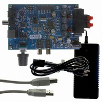
CRD4525-Q1
Description
REFERENCE BOARD FOR CS4525 PWM
Manufacturer
Cirrus Logic Inc
Series
Popguard®r
Specifications of CRD4525-Q1
Amplifier Type
Class D
Output Type
2-Channel (Stereo)
Max Output Power X Channels @ Load
15W x 2 @ 8 Ohm
Voltage - Supply
12 V ~ 18 V
Operating Temperature
0°C ~ 70°C
Board Type
Fully Populated
Utilized Ic / Part
CS4525
Lead Free Status / RoHS Status
Contains lead / RoHS non-compliant
Other names
598-1586


DS726PP3
DC ELECTRICAL CHARACTERISTICS
AGND = DGND = PGND = 0 V; All voltages with respect to ground; PWM switch rate = 384 kHz; Unless otherwise
specified.
Notes:
DIGITAL INTERFACE SPECIFICATIONS
AGND = DGND = PGND = 0 V; All voltages with respect to ground; Unless otherwise specified.
Notes:
Normal Operation
Power Supply Current
Power Dissipation
Power-Down Mode
Power Supply Current
VD_REG Characteristics
Nominal Voltage
DC current source
VA_REG Characteristics
Nominal Voltage
DC current source
VQ Characteristics
Nominal Voltage
Output Impedance
DC current source/sink
Filt+ Nominal Voltage
Power Supply Rejection Ratio
Digital Interface Signal Characteristics
High-Level Input Voltage
Low-Level Input Voltage
High-Level Output Voltage
Low-Level Output Voltage
Input Leakage Current
Input Capacitance
PWM_SIGx Characteristics
High-Level PWM_SIGx Output Voltage
Low-Level PWM_SIGx Output Voltage
18. Normal operation is defined as RST = HI.
19. Power-Down Mode is defined as RST = LOW with all input lines held static.
20. The DC current drain represents the allowed current from the VQ pin due to typical leakage through
21. Valid with the recommended capacitor values on FILT+ and VQ. Increasing the capacitance will
22. Digital interface signals include all pins sourced from the VD supply as shown in
the electrolytic de-coupling capacitors.
increase the PSRR.
Characteristics” on page
(Note 18)
(Note 19)
Parameters
(Note 21)
Parameters
12.
(Note 22)
I
I
I
I
o
o
o
o
=2 mA
=2 mA
=2 mA
=2 mA
VD = 3.3 V
VD = 3.3 V
VD = 3.3 V
(Note 20)
Symbol
V
V
V
V
OHPS
V
V
OLPS
60 Hz
I
1 kHz
OH
OL
in
IH
IL
0.75*VD_REG
0.90*VD_REG
Min
2.25
2.25
-
-
-
-
-
-
-
-
-
-
-
0.90*VD
Min
-
-
-
-
-
0.5*VA_REG
VA_REG
Typ
180
2.8
2.5
2.5
54
23
60
40
-
-
-
0.20*VD_REG
Max
±10
0.2
0.2
“Digital I/O Pin
8
-
-
-
Max
2.75
2.75
10
3
1
-
-
-
-
-
-
-
-
CS4525
Units
uA
Units
pF
V
V
V
V
V
V
mW
mA
mA
mA
mA
kΩ
µA
dB
dB
V
V
V
V
25
Related parts for CRD4525-Q1
Image
Part Number
Description
Manufacturer
Datasheet
Request
R

Part Number:
Description:
Development Kit
Manufacturer:
Cirrus Logic Inc
Datasheet:
Part Number:
Description:
Development Kit
Manufacturer:
Cirrus Logic Inc
Datasheet:


Part Number:
Description:
High-efficiency PFC + Fluorescent Lamp Driver Reference Design
Manufacturer:
Cirrus Logic Inc
Datasheet:
Part Number:
Description:
Development Kit
Manufacturer:
Cirrus Logic Inc
Datasheet:
Part Number:
Description:
Development Kit
Manufacturer:
Cirrus Logic Inc
Datasheet:

Part Number:
Description:
Development Kit
Manufacturer:
Cirrus Logic Inc
Datasheet:
Part Number:
Description:
Development Kit
Manufacturer:
Cirrus Logic Inc
Datasheet:
Part Number:
Description:
Development Kit
Manufacturer:
Cirrus Logic Inc
Datasheet:
Part Number:
Description:
Audio Modules & Development Tools EvalBd 30W Qd Hlf- Brdg Dig Amp Pwr Stg
Manufacturer:
Cirrus Logic Inc
Datasheet:

Part Number:
Description:
EVALUATION BOARD FOR CS8427
Manufacturer:
Cirrus Logic Inc
Datasheet:

Part Number:
Description:
BOARD EVAL FOR CS8416 RCVR
Manufacturer:
Cirrus Logic Inc
Datasheet:

Part Number:
Description:
EVALUATION BOARD FOR CS8420
Manufacturer:
Cirrus Logic Inc
Datasheet:

Part Number:
Description:
KIT DEVELOPMENT EP9315 ARM9
Manufacturer:
Cirrus Logic Inc
Datasheet: