CRD4525-Q1 Cirrus Logic Inc, CRD4525-Q1 Datasheet - Page 7
CRD4525-Q1
Manufacturer Part Number
CRD4525-Q1
Description
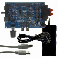
REFERENCE BOARD FOR CS4525 PWM
Manufacturer
Cirrus Logic Inc
Series
Popguard®r
Specifications of CRD4525-Q1
Amplifier Type
Class D
Output Type
2-Channel (Stereo)
Max Output Power X Channels @ Load
15W x 2 @ 8 Ohm
Voltage - Supply
12 V ~ 18 V
Operating Temperature
0°C ~ 70°C
Board Type
Fully Populated
Utilized Ic / Part
CS4525
Lead Free Status / RoHS Status
Contains lead / RoHS non-compliant
Other names
598-1586


CS4525
Figure 16.Bi-Quad Filter Architecture ........................................................................................................ 33
Figure 17.Peak Signal Detection & Limiting .............................................................................................. 37
Figure 18.Foldback Process ..................................................................................................................... 40
Figure 19.Popguard Connection Diagram ................................................................................................. 46
Figure 20.2-Channel Full-Bridge PWM Output Delay ............................................................................... 50
Figure 21.3-Channel PWM Output Delay .................................................................................................. 50
Figure 22.Typical SYS_CLK Input Clocking Configuration ....................................................................... 54
Figure 23.Hardware Mode PWM Output Delay ......................................................................................... 55
Figure 24.Hardware Mode Digital Signal Flow .......................................................................................... 56
Figure 25.Foldback Process ..................................................................................................................... 57
Figure 26.Output Filter - Half-Bridge ......................................................................................................... 59
Figure 27.Output Filter - Full-Bridge .......................................................................................................... 60
Figure 28.Recommended Unity Gain Input Filter ...................................................................................... 61
Figure 29.Recommended 2 V
Input Filter ........................................................................................... 61
RMS
Figure 30.I²S Serial Audio Formats ........................................................................................................... 62
Figure 31.Left-Justified Serial Audio Formats ........................................................................................... 62
Figure 32.Right-Justified Serial Audio Formats ......................................................................................... 63
Figure 33.Control Port Timing, I²C Write ................................................................................................... 64
Figure 34.Control Port Timing, I²C Read ................................................................................................... 64
LIST OF TABLES
Table 1. I/O Power Rails ........................................................................................................................... 12
Table 2. Bass Shelving Filter Corner Frequencies .................................................................................... 31
Table 3. Treble Shelving Filter Corner Frequencies ................................................................................. 32
Table 4. Bass Management Cross-Over Frequencies .............................................................................. 35
Table 5. 2-Way Cross-Over Frequencies .................................................................................................. 42
Table 6. Auxiliary Serial Port Data Output ................................................................................................ 43
Table 7. Nominal Switching Frequencies of the Auxiliary Serial Output ................................................... 43
Table 8. PWM Power Output Configurations ............................................................................................ 45
Table 9. Typical Ramp Times for Various VP Voltages ............................................................................ 46
Table 10. PWM Logic-Level Output Configurations .................................................................................. 49
Table 11. PWM Output Switching Rates and Quantization Levels ........................................................... 51
Table 12. Output of PWM_SIG Outputs .................................................................................................... 52
Table 13. SYS_CLK Frequency Selection ................................................................................................ 54
Table 14. Input Source Selection .............................................................................................................. 55
Table 15. Serial Audio Interface Format Selection .................................................................................... 55
Table 16. Thermal Foldback Enable Selection ......................................................................................... 57
Table 17. PWM Output Switching Rates and Quantization Levels ........................................................... 58
Table 18. Low-Pass Filter Components - Half-Bridge ............................................................................... 59
Table 19. DC-Blocking Capacitors Values - Half-Bridge ........................................................................... 59
Table 20. Low-Pass Filter Components - Full-Bridge ............................................................................... 60
Table 21. Power Supply Configuration and Settings ................................................................................. 63
DS726PP3
7
Related parts for CRD4525-Q1
Image
Part Number
Description
Manufacturer
Datasheet
Request
R

Part Number:
Description:
Development Kit
Manufacturer:
Cirrus Logic Inc
Datasheet:
Part Number:
Description:
Development Kit
Manufacturer:
Cirrus Logic Inc
Datasheet:


Part Number:
Description:
High-efficiency PFC + Fluorescent Lamp Driver Reference Design
Manufacturer:
Cirrus Logic Inc
Datasheet:
Part Number:
Description:
Development Kit
Manufacturer:
Cirrus Logic Inc
Datasheet:
Part Number:
Description:
Development Kit
Manufacturer:
Cirrus Logic Inc
Datasheet:

Part Number:
Description:
Development Kit
Manufacturer:
Cirrus Logic Inc
Datasheet:
Part Number:
Description:
Development Kit
Manufacturer:
Cirrus Logic Inc
Datasheet:
Part Number:
Description:
Development Kit
Manufacturer:
Cirrus Logic Inc
Datasheet:
Part Number:
Description:
Audio Modules & Development Tools EvalBd 30W Qd Hlf- Brdg Dig Amp Pwr Stg
Manufacturer:
Cirrus Logic Inc
Datasheet:

Part Number:
Description:
EVALUATION BOARD FOR CS8427
Manufacturer:
Cirrus Logic Inc
Datasheet:

Part Number:
Description:
BOARD EVAL FOR CS8416 RCVR
Manufacturer:
Cirrus Logic Inc
Datasheet:

Part Number:
Description:
EVALUATION BOARD FOR CS8420
Manufacturer:
Cirrus Logic Inc
Datasheet:

Part Number:
Description:
KIT DEVELOPMENT EP9315 ARM9
Manufacturer:
Cirrus Logic Inc
Datasheet: