DM300023 Microchip Technology, DM300023 Datasheet - Page 140
DM300023
Manufacturer Part Number
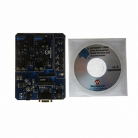
DM300023
Description
KIT DEMO DSPICDEM SMPS BUCK
Manufacturer
Microchip Technology
Series
dsPIC™r
Datasheets
1.AC164335.pdf
(286 pages)
2.DM300023.pdf
(22 pages)
3.DM300023.pdf
(18 pages)
4.DM300023.pdf
(50 pages)
5.DM300023.pdf
(16 pages)
Specifications of DM300023
Main Purpose
DC/DC, Step Down
Outputs And Type
2, Non-Isolated
Voltage - Input
7 ~ 15V
Regulator Topology
Buck
Board Type
Fully Populated
Utilized Ic / Part
dsPIC30F2020
Processor To Be Evaluated
dsPIC30F202x/1010
Interface Type
RS-232
Lead Free Status / RoHS Status
Lead free / RoHS Compliant
Current - Output
-
Voltage - Output
-
Power - Output
-
Frequency - Switching
-
Lead Free Status / Rohs Status
Lead free / RoHS Compliant
Available stocks
Company
Part Number
Manufacturer
Quantity
Price
Company:

Part Number:
DM300023
Manufacturer:
Microchip Technology
Quantity:
135
Company:
Part Number:
DM300023
Manufacturer:
MICROCHIP
Quantity:
12 000


dsPIC30F1010/202X
12.34.3 APPLICATION OF PUSH-PULL PWM
Push-Pull PWM mode is typically used in transformer
coupled circuits to ensure that no net DC currents flow
through the transformer. Push-Pull mode ensures that
the same duty cycle PWM pulse is applied to the
transformer windings in alternate directions, as shown
in Figure 12-24.
FIGURE 12-24:
DS70178C-page 138
PWM1H
PWM1L
+V
+V
PWH1H
PWH1L
PWM1H
+
IN
+V
IN
PWM1L
+
IN
PWM1L
PWM1H
Dead Time
MODE
PWH1L
PWH1H
T
ON
Period
APPLICATIONS OF PUSH-
PULL PWM MODE
T1
T1
T
OFF
Dead Time
Half Bridge Converter
Push-Pull Buck Converter
T1
Full Bridge Converter
T
ON
Period
L1
L1
T
Dead Time
L1
OFF
V
OUT
+
V
V
OUT
+
OUT
+
Preliminary
12.34.4 APPLICATION OF MULTI-PHASE PWM
Multi-Phase PWM mode is often used in DC/DC con-
verters that must handle very fast load current tran-
sients and fit into tight spaces. A multi-phase converter
is essentially a parallel array of buck converters that
are operated slightly out of phase of each other, as
shown in Figure 12-25. The multiple phases create an
effective switching speed equal to the sum of the indi-
vidual converters. If a single phase is operating with a
333 KHz PWM frequency, then the effective switching
frequency for the circuit is 1 MHz. This high switching
frequency greatly reduces output capacitor size
requirements and improves load transient response.
FIGURE 12-25:
PWM1H
PWM1L
PWM1H
PWM1L
PWM2H
PWM2L
PWM3H
PWM3L
+
V
IN
MODE
PWM2H
PWM1L
L1
APPLICATIONS OF MULTI-
PHASE PWM MODE
© 2006 Microchip Technology Inc.
PWM3H
PWM1L
L2
Multiphase DC/DC
L3
Converter
V
+
OUT
Related parts for DM300023
Image
Part Number
Description
Manufacturer
Datasheet
Request
R

Part Number:
Description:
Manufacturer:
Microchip Technology Inc.
Datasheet:
Part Number:
Description:
Manufacturer:
Microchip Technology Inc.
Datasheet:
Part Number:
Description:
Manufacturer:
Microchip Technology Inc.
Datasheet:
Part Number:
Description:
Manufacturer:
Microchip Technology Inc.
Datasheet:
Part Number:
Description:
Manufacturer:
Microchip Technology Inc.
Datasheet:
Part Number:
Description:
Manufacturer:
Microchip Technology Inc.
Datasheet:
Part Number:
Description:
Manufacturer:
Microchip Technology Inc.
Datasheet:
Part Number:
Description:
Manufacturer:
Microchip Technology Inc.
Datasheet: