DM300023 Microchip Technology, DM300023 Datasheet - Page 99
DM300023
Manufacturer Part Number
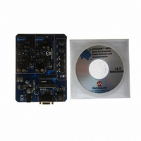
DM300023
Description
KIT DEMO DSPICDEM SMPS BUCK
Manufacturer
Microchip Technology
Series
dsPIC™r
Datasheets
1.AC164335.pdf
(286 pages)
2.DM300023.pdf
(22 pages)
3.DM300023.pdf
(18 pages)
4.DM300023.pdf
(50 pages)
5.DM300023.pdf
(16 pages)
Specifications of DM300023
Main Purpose
DC/DC, Step Down
Outputs And Type
2, Non-Isolated
Voltage - Input
7 ~ 15V
Regulator Topology
Buck
Board Type
Fully Populated
Utilized Ic / Part
dsPIC30F2020
Processor To Be Evaluated
dsPIC30F202x/1010
Interface Type
RS-232
Lead Free Status / RoHS Status
Lead free / RoHS Compliant
Current - Output
-
Voltage - Output
-
Power - Output
-
Frequency - Switching
-
Lead Free Status / Rohs Status
Lead free / RoHS Compliant
Available stocks
Company
Part Number
Manufacturer
Quantity
Price
Company:

Part Number:
DM300023
Manufacturer:
Microchip Technology
Quantity:
135
Company:
Part Number:
DM300023
Manufacturer:
MICROCHIP
Quantity:
12 000


10.0
This section describes the Input Capture module and
associated operational modes. The features provided
by this module are useful in applications requiring Fre-
quency (Period) and Pulse measurement. Figure 10-1
depicts a block diagram of the Input Capture module.
Input capture is useful for such modes as:
• Frequency/Period/Pulse Measurements
• Additional sources of External Interrupts
FIGURE 10-1:
© 2006 Microchip Technology Inc.
Note: This data sheet summarizes features of this group
of dsPIC30F devices and is not intended to be a complete
reference source. For more information on the CPU,
peripherals, register descriptions and general device
functionality, refer to the “dsPIC30F Family Reference
Manual” (DS70046).
ICx
Pin
Note:
INPUT CAPTURE MODULE
Where ‘x’ is shown, reference is made to the registers or bits associated to the respective input
capture channels 1 through N.
Prescaler
1, 4, 16
3
INPUT CAPTURE MODE BLOCK DIAGRAM
Data Bus
ICxCON
Mode Select
ICM<2:0>
ICBNE, ICOV
Synchronizer
Clock
ICI<1:0>
Preliminary
Detection
Logic
Edge
From General Purpose Timer Module
The key operational features of the Input Capture
module are:
• Simple Capture Event mode
• Timer2 and Timer3 mode selection
• Interrupt on input capture event
These operating modes are determined by setting the
appropriate bits in the ICxCON register (where x =
1,2,...,N). The dsPIC DSC devices contain up to 8
capture channels, (i.e., the maximum value of N is 8).
Interrupt
Logic
Note:
dsPIC30F1010/202X
Set Flag
Set Flag
ICxIF
ICxIF
The dsPIC30F1010 devices does not fea-
ture a Input Capture module. The
dsPIC30F202X devices have one capture
input – IC1. The naming of this capture
channel is intentional and preserves soft-
ware compatibility with other dsPIC DSC
devices.
FIFO
Logic
R/W
T2_CNT
1
ICxBUF
16
DS70178C-page 97
0
T3_CNT
16
ICTMR
Related parts for DM300023
Image
Part Number
Description
Manufacturer
Datasheet
Request
R

Part Number:
Description:
Manufacturer:
Microchip Technology Inc.
Datasheet:
Part Number:
Description:
Manufacturer:
Microchip Technology Inc.
Datasheet:
Part Number:
Description:
Manufacturer:
Microchip Technology Inc.
Datasheet:
Part Number:
Description:
Manufacturer:
Microchip Technology Inc.
Datasheet:
Part Number:
Description:
Manufacturer:
Microchip Technology Inc.
Datasheet:
Part Number:
Description:
Manufacturer:
Microchip Technology Inc.
Datasheet:
Part Number:
Description:
Manufacturer:
Microchip Technology Inc.
Datasheet:
Part Number:
Description:
Manufacturer:
Microchip Technology Inc.
Datasheet: