DM300023 Microchip Technology, DM300023 Datasheet - Page 173
DM300023
Manufacturer Part Number
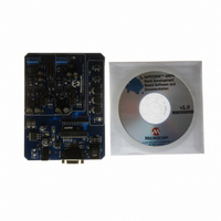
DM300023
Description
KIT DEMO DSPICDEM SMPS BUCK
Manufacturer
Microchip Technology
Series
dsPIC™r
Datasheets
1.AC164335.pdf
(286 pages)
2.DM300023.pdf
(22 pages)
3.DM300023.pdf
(18 pages)
4.DM300023.pdf
(50 pages)
5.DM300023.pdf
(16 pages)
Specifications of DM300023
Main Purpose
DC/DC, Step Down
Outputs And Type
2, Non-Isolated
Voltage - Input
7 ~ 15V
Regulator Topology
Buck
Board Type
Fully Populated
Utilized Ic / Part
dsPIC30F2020
Processor To Be Evaluated
dsPIC30F202x/1010
Interface Type
RS-232
Lead Free Status / RoHS Status
Lead free / RoHS Compliant
Current - Output
-
Voltage - Output
-
Power - Output
-
Frequency - Switching
-
Lead Free Status / Rohs Status
Lead free / RoHS Compliant
Available stocks
Company
Part Number
Manufacturer
Quantity
Price
Company:

Part Number:
DM300023
Manufacturer:
Microchip Technology
Quantity:
135
Company:
Part Number:
DM300023
Manufacturer:
MICROCHIP
Quantity:
12 000


REGISTER 16-1:
© 2006 Microchip Technology Inc.
bit 15
bit 7
Legend:
R = Readable bit
-n = Value at POR
bit 15
bit 14
bit 13
bit 12-11
bit 10
bit 9
bit 8
bit 7
bit 6
bit 5
bit 4-3
ADON
R/W-0
R/W-0
EIE
ADON: A/D Operating Mode bit
1 = A/D converter module is operating
0 = A/D converter is off
Unimplemented: Read as ‘0’
ADSIDL: Stop in Idle Mode bit
1 = Discontinue module operation when device enters Idle mode
0 = Continue module operation in Idle mode
Unimplemented: Read as ‘0’
GSWTRG: Global Software Trigger bit
When this bit is set by the user, it will trigger conversions if selected by the TRGSRC<4:0> bits in the
ADCPCx registers. This bit must be cleared by the user prior to initiating another global trigger (i.e.,
this bit is not auto-clearing).
Unimplemented: Read as ‘0’
FORM: Data Output Format bit
1 = Fractional (D
0 = Integer
EIE: Early Interrupt Enable bit
1 = Interrupt is generated after first conversion is completed
0 = Interrupt is generated after second conversion is completed
ORDER: Conversion Order bit
1 = Odd numbered analog input is converted first, followed by conversion of even numbered input
0 = Even numbered analog input is converted first, followed by conversion of odd numbered input
SEQSAMP: Sequential Sample Enable.
1 = Shared S&H is sampled at the start of the second conversion if ORDER = 0. If ORDER = 1, then
0 = Shared S&H is sampled at the same time the dedicated S&H is sampled if the shared S&H is not
Unimplemented: Read as ‘0’
Note:
Note:
ORDER
R/W-0
the shared S&H is sampled at the start of the first conversion.
currently busy with an existing conversion process. If the shared S&H is busy at the time the
dedicated S&H is sampled, then the shared S&H will sample at the start of the new conversion
cycle
U-0
—
A/D CONTROL REGISTER (ADCON)
This control bit can only be changed while ADC is disabled (ADON = 0).
This control bit can only be changed while ADC is disabled (ADON = 0).
W = Writable bit
‘1’ = Bit is set
(D
SEQSAMP
OUT
ADSIDL
OUT
R/W-0
R/W-0
= 0000 00dd dddd dddd)
= dddd dddd dd00 0000)
Preliminary
U-0
U-0
—
—
U = Unimplemented bit, read as ‘0’
‘0’ = Bit is cleared
U-0
U-0
dsPIC30F1010/202X
—
—
GSWTRG
R/W-0
R/W-0
ADCS<2:0>
x = Bit is unknown
R/W-1
U-0
—
DS70178C-page 171
FORM
R/W-0
R/W-1
bit 8
bit 0
Related parts for DM300023
Image
Part Number
Description
Manufacturer
Datasheet
Request
R

Part Number:
Description:
Manufacturer:
Microchip Technology Inc.
Datasheet:
Part Number:
Description:
Manufacturer:
Microchip Technology Inc.
Datasheet:
Part Number:
Description:
Manufacturer:
Microchip Technology Inc.
Datasheet:
Part Number:
Description:
Manufacturer:
Microchip Technology Inc.
Datasheet:
Part Number:
Description:
Manufacturer:
Microchip Technology Inc.
Datasheet:
Part Number:
Description:
Manufacturer:
Microchip Technology Inc.
Datasheet:
Part Number:
Description:
Manufacturer:
Microchip Technology Inc.
Datasheet:
Part Number:
Description:
Manufacturer:
Microchip Technology Inc.
Datasheet: