DM300023 Microchip Technology, DM300023 Datasheet - Page 141
DM300023
Manufacturer Part Number
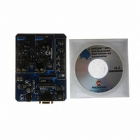
DM300023
Description
KIT DEMO DSPICDEM SMPS BUCK
Manufacturer
Microchip Technology
Series
dsPIC™r
Datasheets
1.AC164335.pdf
(286 pages)
2.DM300023.pdf
(22 pages)
3.DM300023.pdf
(18 pages)
4.DM300023.pdf
(50 pages)
5.DM300023.pdf
(16 pages)
Specifications of DM300023
Main Purpose
DC/DC, Step Down
Outputs And Type
2, Non-Isolated
Voltage - Input
7 ~ 15V
Regulator Topology
Buck
Board Type
Fully Populated
Utilized Ic / Part
dsPIC30F2020
Processor To Be Evaluated
dsPIC30F202x/1010
Interface Type
RS-232
Lead Free Status / RoHS Status
Lead free / RoHS Compliant
Current - Output
-
Voltage - Output
-
Power - Output
-
Frequency - Switching
-
Lead Free Status / Rohs Status
Lead free / RoHS Compliant
Available stocks
Company
Part Number
Manufacturer
Quantity
Price
Company:

Part Number:
DM300023
Manufacturer:
Microchip Technology
Quantity:
135
Company:
Part Number:
DM300023
Manufacturer:
MICROCHIP
Quantity:
12 000


12.34.5 APPLICATION OF VARIABLE PHASE PWM
Variable phase PWM is used in newer power conver-
sion topologies that are designed to reduce switching
losses. In standard PWM methods, any time a transis-
tor switches between the conducting state and the
nonconducting state (and vice versa), the transistor is
exposed to the full current and voltage condition for
the period of time it takes the transistor to turn on or
off. The power loss (V * I * Tsw * FPWM) becomes
appreciable at high frequencies. The Zero Voltage
Switching (ZVS) and Zero Current Switching (ZVC) cir-
cuit topologies attempt to use quasi-resonant tech-
niques to shift either the voltage or current waveforms
relative to each other. This action either makes the
voltage or the current zero at the time the transistor
turns on or off. If either the current or the voltage is
zero, then there is no switching loss generated.
In variable phase PWM modes, the duty cycle is fixed
at 50%, and the power flow is controlled by varying the
phase relationship between the PWM channels, as
shown in Figure 12-26.
FIGURE 12-26:
© 2006 Microchip Technology Inc.
PWM1H
PWM1H
PWM2L
+V
PWM1L
PWM2H
PWM1H
IN
MODE
Variable Phase Shift
PWM1H
PWM1H
APPLICATION OF
VARIABLE PHASE PWM
MODE
Full Bridge ZVT Converter
T1
V
+
OUT
Preliminary
12.34.6 APPLICATION OF CURRENT RESET PWM
In Current Reset PWM mode, the PWM frequency var-
ies with the load current. This mode is different than
most PWM modes because the user sets the maxi-
mum PWM period, but an external circuit measures
the inductor current. When the inductor current falls
below a specified value, the external current compara-
tor circuit generates a signal that resets the PWM time
base counter. The user specifies a PWM “on” time,
and then some time after the PWM signal becomes
inactive, the inductor current falls below a specified
value and the PWM counter is reset earlier than the
programmed PWM period. This mode is sometimes
called Constant On-Time.
This mode should not be confused with cycle-by-cycle
current-limiting PWM, where the PWM is asserted, an
external circuit generates a current Fault and the PWM
signal is turned off before its programmed duty cycle
would normally turn it off. In this mode, shown in
Figure 12-27, the PWM frequency is fixed per the time
base period.
FIGURE 12-27:
AC
dsPIC30F1010/202X
IN
PWM1H
PWM1H
External current comparator resets PWM counter
MODE
This is a variable frequency PWM mode
I
L
PWM cycle restarts early
Actual Period
+
Programmed Period
T
ON
C
APPLICATION OF
CURRENT RESET PWM
MODE
IN
PWM1H
L
I
L
T
OFF
DS70178C-page 139
D
+
V
C
OUT
OUT
Related parts for DM300023
Image
Part Number
Description
Manufacturer
Datasheet
Request
R

Part Number:
Description:
Manufacturer:
Microchip Technology Inc.
Datasheet:
Part Number:
Description:
Manufacturer:
Microchip Technology Inc.
Datasheet:
Part Number:
Description:
Manufacturer:
Microchip Technology Inc.
Datasheet:
Part Number:
Description:
Manufacturer:
Microchip Technology Inc.
Datasheet:
Part Number:
Description:
Manufacturer:
Microchip Technology Inc.
Datasheet:
Part Number:
Description:
Manufacturer:
Microchip Technology Inc.
Datasheet:
Part Number:
Description:
Manufacturer:
Microchip Technology Inc.
Datasheet:
Part Number:
Description:
Manufacturer:
Microchip Technology Inc.
Datasheet: