EVALSTSR30-60W STMicroelectronics, EVALSTSR30-60W Datasheet - Page 12
EVALSTSR30-60W
Manufacturer Part Number
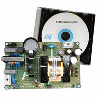
EVALSTSR30-60W
Description
BOARD EVAL USING L6668 & STSR30
Manufacturer
STMicroelectronics
Type
AC/DC Switching Convertersr
Specifications of EVALSTSR30-60W
Mfg Application Notes
EVALSTSR30-60W AppNote
Main Purpose
AC/DC, Primary and Secondary Side
Outputs And Type
1, Isolated
Power - Output
60W
Voltage - Output
12V
Current - Output
5A
Voltage - Input
88 ~ 264VAC
Regulator Topology
Flyback
Frequency - Switching
68kHz
Board Type
Fully Populated
Utilized Ic / Part
L6668, STSR30
Input Voltage
88 V to 264 V
Output Voltage
12 V
Dimensions
120 mm x 75 mm
Product
Power Management Modules
Silicon Manufacturer
ST Micro
Silicon Core Number
L6668 And STSR30
Kit Application Type
Power Management - Voltage Regulator
Application Sub Type
SMPS
Kit Contents
Board
Lead Free Status / RoHS Status
Lead free / RoHS Compliant
For Use With/related Products
L6668, STSR30
Other names
497-6389
EVALSTSR30-60W
EVALSTSR30-60W
Available stocks
Company
Part Number
Manufacturer
Quantity
Price


L6668
4
The L6668 is a versatile current-mode PWM controller specific for offline fixed-frequency, peak-current-
mode-controlled flyback converters.
The device is able to operate in different modes (fig. 34), depending on the converter's load conditions:
1) Fixed frequency at heavy load. In this region the IC operates exactly like a standard current mode control
2) Frequency-foldback mode at medium and light load. As the load is reduced the oscillator frequency is re-
3) Burst-mode control with no or very light load. When the load is extremely light or disconnected, the converter
Figure 34. Multi-mode operation of the L6668
4.1 High-voltage start-up generator
Figure 35 shows the internal schematic of the high-voltage start-up generator (HV generator). It is made
up of a high-voltage N-channel FET, whose gate is biased by a 15 M Ω resistor, with a temperature-com-
pensated current generator connected to its source.
Figure 35. High-voltage start-up generator: internal schematic
The HV generator is physically located on a separate chip, made with BCD off-line technology able to with-
stand 700V, controlled by a low-voltage chip, where all of the control functions reside.
12/23
chip: a relaxation oscillator, externally programmable with a capacitor and a resistor, generates a sawtooth
and releases a clock pulse during the falling edge of the sawtooth; the power switch is turned on by the clock
pulses and is turned off by the control loop.
duced as well by slowing down the charge of the timing capacitor proportionally to the load itself.
will enter a controlled on/off operation with constant peak current. A load decrease will be then translated
into a frequency reduction, which can go down even to few hundred hertz, thus minimizing all frequency-
related losses and making it easier to comply with energy saving regulations. Being the peak current very
low, no issue of audible noise arises.
Application Information
f
sw
0
0
Frequency foldback mode
L6668
Vcc_OK
15 M Ω
CONTROL
HV_EN
P
GND
3
in
1
HV
I
charge
Fixed-frequency mode
I
HV
5
Vcc
Pinmax
Related parts for EVALSTSR30-60W
Image
Part Number
Description
Manufacturer
Datasheet
Request
R

Part Number:
Description:
STMicroelectronics [RIPPLE-CARRY BINARY COUNTER/DIVIDERS]
Manufacturer:
STMicroelectronics
Datasheet:
Part Number:
Description:
STMicroelectronics [LIQUID-CRYSTAL DISPLAY DRIVERS]
Manufacturer:
STMicroelectronics
Datasheet:

Part Number:
Description:
BOARD EVAL FOR MEMS SENSORS
Manufacturer:
STMicroelectronics
Datasheet:
Part Number:
Description:
NPN TRANSISTOR POWER MODULE
Manufacturer:
STMicroelectronics
Datasheet:
Part Number:
Description:
TURBOSWITCH ULTRA-FAST HIGH VOLTAGE DIODE
Manufacturer:
STMicroelectronics
Datasheet:
Part Number:
Description:
Manufacturer:
STMicroelectronics
Datasheet:
Part Number:
Description:
DIODE / SCR MODULE
Manufacturer:
STMicroelectronics
Datasheet:
Part Number:
Description:
DIODE / SCR MODULE
Manufacturer:
STMicroelectronics
Datasheet:
Part Number:
Description:
Search -----> STE16N100
Manufacturer:
STMicroelectronics
Datasheet:
Part Number:
Description:
Search ---> STE53NA50
Manufacturer:
STMicroelectronics
Datasheet:
Part Number:
Description:
NPN Transistor Power Module
Manufacturer:
STMicroelectronics
Datasheet:
Part Number:
Description:
DIODE / SCR MODULE
Manufacturer:
STMicroelectronics
Datasheet: