EVALSTSR30-60W STMicroelectronics, EVALSTSR30-60W Datasheet - Page 2
EVALSTSR30-60W
Manufacturer Part Number
EVALSTSR30-60W
Description
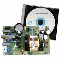
BOARD EVAL USING L6668 & STSR30
Manufacturer
STMicroelectronics
Type
AC/DC Switching Convertersr
Specifications of EVALSTSR30-60W
Mfg Application Notes
EVALSTSR30-60W AppNote
Main Purpose
AC/DC, Primary and Secondary Side
Outputs And Type
1, Isolated
Power - Output
60W
Voltage - Output
12V
Current - Output
5A
Voltage - Input
88 ~ 264VAC
Regulator Topology
Flyback
Frequency - Switching
68kHz
Board Type
Fully Populated
Utilized Ic / Part
L6668, STSR30
Input Voltage
88 V to 264 V
Output Voltage
12 V
Dimensions
120 mm x 75 mm
Product
Power Management Modules
Silicon Manufacturer
ST Micro
Silicon Core Number
L6668 And STSR30
Kit Application Type
Power Management - Voltage Regulator
Application Sub Type
SMPS
Kit Contents
Board
Lead Free Status / RoHS Status
Lead free / RoHS Compliant
For Use With/related Products
L6668, STSR30
Other names
497-6389
EVALSTSR30-60W
EVALSTSR30-60W
Available stocks
Company
Part Number
Manufacturer
Quantity
Price


L6668
2
L6668 is a current-mode primary controller IC, designed to build single-ended converters.
The IC drives the system at fixed frequency at heavy load and an improved Standby function causes a
smooth frequency reduction as the load is progressively reduced. At very light load the device enters a
special operating mode (burst-mode with fixed, externally programmed peak current) that, in addition to
the on-board high-voltage start-up and the very low quiescent current, helps keep low the consumption
from the mains and be compliant with energy saving regulations. To allow meeting compliance with these
standards in power-factor-corrected systems too, an interface with the PFC controller is provided that en-
ables to turn off the pre-regulator when the load level falls below a threshold.
The IC includes also a programmable soft-start, slope compensation for stable operation at duty cycles
greater then 50%, a disable function, a leading edge blanking on current sense to improve noise immunity,
latched disable for OVP or OTP shutdown and an effective two-level OCP able to protect the system even
in case the secondary diode fails short.
Table 2. Absolute Maximum Ratings
Note: 1. ESD immunity for pin 1 is guaranteed up to 900V (Human Body Model).
Table 3. Thermal Data
Figure 3. Pin Connection (Top view)
2/23
V
I
PFC_STOP
Symbol
Symbol
R
PFC_STOP
th j-amb
V
T
P
V
I
Description
---
HV
T
HV
stg
tot
cc
j
Thermal Resistance Junction to AmbientMax
Pin
14
14
5
1
1
IC Supply voltage (Icc = 20 mA)
High-voltage start-up generator voltage range
High-voltage start-up generator current
Analog Inputs & Outputs, except pin 14
Max. sink current (low state)
Max. voltage (open state)
Power Dissipation @Tamb = 50°C
Junction Temperature Operating range
Storage Temperature
HV
HV
HVS
HVS
GND
GND
OUT
OUT
Vcc
Vcc
N.C.
N.C.
DIS
DIS
VREF
VREF
Parameter
1
Parameter
RCT
RCT
S-COMP
S-COMP
PFC_STOP
PFC_STOP
STBY
STBY
ISEN
ISEN
SS
SS
COMP
COMP
SKIPADJ
SKIPADJ
Self-limited
Self-limited
-0.3 to 700
-25 to 150
-55 to 150
-0.3 to 8
Value
120
Value
0.75
16
2
°C/W
Unit
Unit
mA
°C
°C
W
V
V
A
V
V
Related parts for EVALSTSR30-60W
Image
Part Number
Description
Manufacturer
Datasheet
Request
R

Part Number:
Description:
STMicroelectronics [RIPPLE-CARRY BINARY COUNTER/DIVIDERS]
Manufacturer:
STMicroelectronics
Datasheet:
Part Number:
Description:
STMicroelectronics [LIQUID-CRYSTAL DISPLAY DRIVERS]
Manufacturer:
STMicroelectronics
Datasheet:

Part Number:
Description:
BOARD EVAL FOR MEMS SENSORS
Manufacturer:
STMicroelectronics
Datasheet:
Part Number:
Description:
NPN TRANSISTOR POWER MODULE
Manufacturer:
STMicroelectronics
Datasheet:
Part Number:
Description:
TURBOSWITCH ULTRA-FAST HIGH VOLTAGE DIODE
Manufacturer:
STMicroelectronics
Datasheet:
Part Number:
Description:
Manufacturer:
STMicroelectronics
Datasheet:
Part Number:
Description:
DIODE / SCR MODULE
Manufacturer:
STMicroelectronics
Datasheet:
Part Number:
Description:
DIODE / SCR MODULE
Manufacturer:
STMicroelectronics
Datasheet:
Part Number:
Description:
Search -----> STE16N100
Manufacturer:
STMicroelectronics
Datasheet:
Part Number:
Description:
Search ---> STE53NA50
Manufacturer:
STMicroelectronics
Datasheet:
Part Number:
Description:
NPN Transistor Power Module
Manufacturer:
STMicroelectronics
Datasheet:
Part Number:
Description:
DIODE / SCR MODULE
Manufacturer:
STMicroelectronics
Datasheet: