EVALSTSR30-60W STMicroelectronics, EVALSTSR30-60W Datasheet - Page 14
EVALSTSR30-60W
Manufacturer Part Number
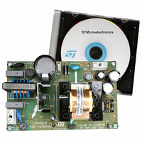
EVALSTSR30-60W
Description
BOARD EVAL USING L6668 & STSR30
Manufacturer
STMicroelectronics
Type
AC/DC Switching Convertersr
Specifications of EVALSTSR30-60W
Mfg Application Notes
EVALSTSR30-60W AppNote
Main Purpose
AC/DC, Primary and Secondary Side
Outputs And Type
1, Isolated
Power - Output
60W
Voltage - Output
12V
Current - Output
5A
Voltage - Input
88 ~ 264VAC
Regulator Topology
Flyback
Frequency - Switching
68kHz
Board Type
Fully Populated
Utilized Ic / Part
L6668, STSR30
Input Voltage
88 V to 264 V
Output Voltage
12 V
Dimensions
120 mm x 75 mm
Product
Power Management Modules
Silicon Manufacturer
ST Micro
Silicon Core Number
L6668 And STSR30
Kit Application Type
Power Management - Voltage Regulator
Application Sub Type
SMPS
Kit Contents
Board
Lead Free Status / RoHS Status
Lead free / RoHS Compliant
For Use With/related Products
L6668, STSR30
Other names
497-6389
EVALSTSR30-60W
EVALSTSR30-60W
Available stocks
Company
Part Number
Manufacturer
Quantity
Price


L6668
At converter power-down the system will lose regulation as soon as the input voltage is so low that either
peak current or maximum duty cycle limitation is tripped. Vcc will then drop and stop IC activity as it falls
below the UVLO threshold (8.7V typ.).
The Vcc_OK signal is de-asserted as the Vcc voltage goes below a threshold Vcc
5V. The HV generator can now restart but, if Vin < V
too and the HV generator is disabled.
This prevents converter's re-start attempts and ensures monotonic output voltage decay at power-down.
The low restart threshold Vcc
have a very low repetition rate, as shown in the timing diagram of figure 37, and that the converter will
work safely with extremely low power throughput.
4.2 Frequency Foldback Block and operation at medium/light load
At heavy load, namely as the voltage on pin COMP (V
frequency like a standard current mode PWM controller.
As the load is reduced, and the V
maximum load in a fully DCM system), the oscillator frequency can be made dependent on converter's
load conditions - the lower the load, the lower the frequency and vice versa.
Figure 38. Frequency foldback function: oscillator frequency is a function of COMP voltage
This is done by adding an external resistor R
vates the circuit shown in figure 38.
When V
nected to a current sink, tracks V
through the STBY pin.
In this way the rate of rise of the voltage across C
the lower V
high impedance and the oscillator frequency f
be then calculated as it is usually done with this type of oscillator:
14/23
L6668
L6668
COMP
COMP
COMP
COMP
3.0V
3.0V
+
+
-
-
is below 3 V (oscillator's peak voltage) the voltage on the STBY pin, which is internally con-
the lower the frequency. Instead, when V
restart
OSCILLATOR
OSCILLATOR
COMP
COMP
ensures that, during short circuits, the restart attempts of the L6668 will
and then some of the current that charges C
voltage falls below 3V (approximately corresponding to 50% of the
13
13
16
16
8
8
RCT
RCT
STBY
STBY
Vref
Vref
osc
STBY
R
T
R
R
T
will be determined by R
C
T
T
is slowed down and the oscillator frequency decreased,
between pins RCT (#16) and STBY (#13), which acti-
T
=
instart
R
R
COMP
C
C
STBY
STBY
---------
f
1.4
T
T
os c
, as shown in figure 36, HV_EN is de-asserted
COMP
) is higher than 3V, the device works at a fixed
f
f
osc
osc
is greater than 3 V the STBY pin features
T
1.4
1.4
and C
R
R
STBY
STBY
T
. These components can
T
restart
is diverted to ground
3.0
3.0
located at about
4.4
4.4
V
V
COMP
COMP
Related parts for EVALSTSR30-60W
Image
Part Number
Description
Manufacturer
Datasheet
Request
R

Part Number:
Description:
STMicroelectronics [RIPPLE-CARRY BINARY COUNTER/DIVIDERS]
Manufacturer:
STMicroelectronics
Datasheet:
Part Number:
Description:
STMicroelectronics [LIQUID-CRYSTAL DISPLAY DRIVERS]
Manufacturer:
STMicroelectronics
Datasheet:

Part Number:
Description:
BOARD EVAL FOR MEMS SENSORS
Manufacturer:
STMicroelectronics
Datasheet:
Part Number:
Description:
NPN TRANSISTOR POWER MODULE
Manufacturer:
STMicroelectronics
Datasheet:
Part Number:
Description:
TURBOSWITCH ULTRA-FAST HIGH VOLTAGE DIODE
Manufacturer:
STMicroelectronics
Datasheet:
Part Number:
Description:
Manufacturer:
STMicroelectronics
Datasheet:
Part Number:
Description:
DIODE / SCR MODULE
Manufacturer:
STMicroelectronics
Datasheet:
Part Number:
Description:
DIODE / SCR MODULE
Manufacturer:
STMicroelectronics
Datasheet:
Part Number:
Description:
Search -----> STE16N100
Manufacturer:
STMicroelectronics
Datasheet:
Part Number:
Description:
Search ---> STE53NA50
Manufacturer:
STMicroelectronics
Datasheet:
Part Number:
Description:
NPN Transistor Power Module
Manufacturer:
STMicroelectronics
Datasheet:
Part Number:
Description:
DIODE / SCR MODULE
Manufacturer:
STMicroelectronics
Datasheet: