EVAL-ADUC812QS Analog Devices Inc, EVAL-ADUC812QS Datasheet - Page 20
EVAL-ADUC812QS
Manufacturer Part Number
EVAL-ADUC812QS
Description
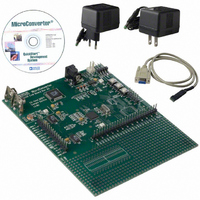
KIT DEV FOR ADUC812 QUICK START
Manufacturer
Analog Devices Inc
Series
QuickStart™ Kitr
Type
MCUr
Datasheet
1.EVAL-ADUC812QS.pdf
(60 pages)
Specifications of EVAL-ADUC812QS
Rohs Status
RoHS non-compliant
Contents
Evaluation Board, Power Supply, Cable, Software and Documentation
For Use With/related Products
ADuC812


ADuC812
ECON—Flash/EE Memory Control SFR
This SFR acts as a command interpreter and may be written
with one of five command modes to enable various read, pro-
gram, and erase cycles as detailed in Table VII.
Command Byte
01H
02H
03H
04H
05H
06H
07H to FFH
Flash/EE Memory Timing
The typical program/erase times for the Flash/EE data
memory are:
Erase Full Array (640 Bytes) – 20 ms
Erase Single Page (4 Bytes)
Program Page (4 Bytes)
Read Page (4 Bytes)
Flash/EE erase and program timing is derived from the master
clock. When using a master clock frequency of 11.0592 MHz, it
is not necessary to write to the ETIM registers at all. However,
when operating at other master clock frequencies (f
must change the values of ETIM1 and ETIM2 to avoid degrad-
ing data Flash/EE endurance and retention. ETIM1 and ETIM2
form a 16-bit word, ETIM2 being the high byte and ETIM1 the
low byte. The value of this 16-bit word must be set as follows to
ensure optimum data Flash/EE endurance and retention.
ETIM3 should always remain at its default value of 201 dec/C9 hex.
Table VII. ECON—Flash/EE Memory Control Register
Command Modes
ETIM2, ETIM1 = 100 µs × f
Command Mode
READ COMMAND
Results in four bytes being read into
EDATA1–4 from memory page address
contained in EADRL.
PROGRAM COMMAND
Results in four bytes (EDATA1–4) being
written to memory page address in EADRL.
This write command assumes the designated
“write” page has been pre-erased.
RESERVED FOR INTERNAL USE
03H should not be written to the
ECON SFR.
VERIFY COMMAND
Allows the user to verify if data in EDATA1–4
is contained in page address designated by
EADRL.
A subsequent read of the ECON SFR will
result in a zero being read if the verification
is valid; a nonzero value will be read to
indicate an invalid verification.
ERASE COMMAND
Results in an erase of the 4-byte page
designated in EADRL.
ERASE-ALL COMMAND
Results in erase of the full Flash/EE data
memory 160-page (640 bytes) array.
RESERVED COMMANDS
Commands reserved for future use.
– 20 ms
– 250 µs
– Within Single Instruction Cycle
CLK
CLK
), you
–20–
Using the Flash/EE Memory Interface
As with all Flash/EE memory architectures, the array can be pro-
grammed in system at a byte level, although it must be erased
first, the erasure being performed in page blocks (4-byte pages
in this case).
A typical access to the Flash/EE array will involve setting up the
page address to be accessed in the EADRL SFR, configuring the
EDATA1–4 with data to be programmed to the array (the
EDATA SFRs will not be written for read accesses), and finally
writing the ECON command word that initiates one of the six
modes shown in Table VII. It should be noted that a given
mode of operation is initiated as soon as the command word is
written to the ECON SFR. The core microcontroller operation
on the ADuC812 is idled until the requested Program/Read or
Erase mode is completed.
In practice, this means that even though the Flash/EE memory
mode of operation is typically initiated with a two-machine cycle
MOV instruction (to write to the ECON SFR), the next instruction
will not be executed until the Flash/EE operation is complete
(250 µs or 20 ms later). This means that the core will not respond
to Interrupt requests until the Flash/EE operation is complete,
although the core peripheral functions like Counter/Timers will
continue to count and time as configured throughout this pseudo-
idle period.
Erase-All
Although the 640-byte user Flash/EE array is shipped from the
factory pre-erased, i.e., byte locations set to FFH, it is nonetheless
good programming practice to include an erase-all routine as
part of any configuration/setup code running on the ADuC812.
An ERASE-ALL command consists of writing 06H to the
ECON SFR, which initiates an erase of all 640 byte locations in
the Flash/EE array. This command coded in 8051 assembly
would appear as:
MOV ECON, #06H
Program a Byte
In general terms, a byte in the Flash/EE array can only be pro-
grammed if it has previously been erased. To be more specific, a
byte can only be programmed if it already holds the value FFH.
Because of the Flash/EE architecture, this erasure must happen
at a page level; therefore, a minimum of four bytes (1 page) will
be erased when an erase command is initiated. A more specific
example of the Program-Byte process is shown below. In this
example, the user writes F3H into the second byte on Page 03H
of the Flash/EE data memory space while preserving the other
three bytes already in this page. As the user is only required to
modify one of the page bytes, the full page must be first read so that
this page can then be erased without the existing data being lost.
This example, coded in 8051 assembly, would appear as:
MOV
MOV
MOV
MOV
MOV
EADRL, #03H
ECON, #01H
EDATA2, #0F3H
ECON, #05H
ECON, #02H
; Erase all Command
; 20 ms Duration
; Set Page Address Pointer
; Read Page
; Write New Byte
; Erase Page
; Write Page (Program
Flash/EE)
REV. E
Related parts for EVAL-ADUC812QS
Image
Part Number
Description
Manufacturer
Datasheet
Request
R


Part Number:
Description:
BOARD EVAL FOR SI270X-A
Manufacturer:
Silicon Laboratories Inc
Datasheet:

Part Number:
Description:
BUCK CONV REF DESIGN KIT IP1201
Manufacturer:
International Rectifier
Datasheet:
Part Number:
Description:
BOARD DEMO SYNC DUAL BUCK CNVTER
Manufacturer:
International Rectifier
Datasheet:
Part Number:
Description:
BOARD DEMO SYNC BUCK CONVETER
Manufacturer:
International Rectifier
Datasheet:

Part Number:
Description:
EVALBOARD/EB Omnidirectional microphone - Analog
Manufacturer:
Analog Devices
Datasheet:
Part Number:
Description:
EVALBOARD/EB Omnidirectional microphone - Analog
Manufacturer:
Analog Devices
Datasheet:


Part Number:
Description:
BOARD EVAL LED DRIVER LT3756
Manufacturer:
Linear Technology
Datasheet:

Part Number:
Description:
BOARD EVAL FOR AD7741/7742
Manufacturer:
Analog Devices Inc
Datasheet:

Part Number:
Description:
±1.7g Dual-Axis IMEMS Accelerometer Evaluation Board
Manufacturer:
Analog Devices Inc
Datasheet:

Part Number:
Description:
IC MULTIPLIER ANALOG 8-SOIC T/R
Manufacturer:
Analog Devices Inc
Datasheet:

Part Number:
Description:
IC ANALOG MULTIPLIER 8-DIP
Manufacturer:
Analog Devices Inc
Datasheet:
Part Number:
Description:
IC ANALOG MULTIPLIER 8-SOIC
Manufacturer:
Analog Devices Inc
Datasheet:
Part Number:
Description:
IC ANALOG MULTIPLIER 8-DIP
Manufacturer:
Analog Devices Inc
Datasheet: