EVAL-ADUC812QS Analog Devices Inc, EVAL-ADUC812QS Datasheet - Page 24
EVAL-ADUC812QS
Manufacturer Part Number
EVAL-ADUC812QS
Description
KIT DEV FOR ADUC812 QUICK START
Manufacturer
Analog Devices Inc
Series
QuickStart™ Kitr
Type
MCUr
Datasheet
1.EVAL-ADUC812QS.pdf
(60 pages)
Specifications of EVAL-ADUC812QS
Rohs Status
RoHS non-compliant
Contents
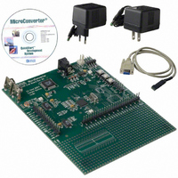
Evaluation Board, Power Supply, Cable, Software and Documentation
For Use With/related Products
ADuC812


ADuC812
WDCON
SFR Address
Power-On Default Value
Bit Addressable
Bit
7
6
5
4
3
2
1
0
Example
To set up the watchdog timer for a timeout period of 2048 ms,
the following code would be used:
MOV
SETB
To prevent the watchdog timer from timing out, the timer
refresh bits need to be set before 2.048 seconds has elapsed.
SETB
SETB
WATCHDOG TIMER
The purpose of the watchdog timer is to generate a device reset
within a reasonable amount of time if the ADuC812 enters an
erroneous state, possibly due to a programming error. The Watch-
dog function can be disabled by clearing the WDE (Watchdog
Enable) bit in the Watchdog Control (WDCON) SFR. When
enabled, the watchdog circuit will generate a system reset if the
P
R
E
WDCON,#0E0h
WDE
WDR1
WDR2
2
Name
PRE2
PRE1
PRE0
—
WDR1
WDR2
WDS
WDE
P
R
E
;refresh watchdog timer..
; ..bits must be set in this
;order
1
;2.048 second
;timeout period
;enable watchdog timer
Watchdog Timer
Control Register
C0H
00H
Yes
P
Description
Watchdog Timer Prescale Bits.
PRE2
0
0
0
0
1
1
1
1
Not Used.
Watchdog Timer Refresh Bits. Set sequentially to refresh the watchdog timer.
Watchdog Status Bit.
Set by the Watchdog Controller to indicate that a watchdog timeout has occurred.
Cleared by writing a “0” or by an external hardware reset. It is not cleared by a watchdog reset.
Watchdog Enable Bit.
Set by user to enable the watchdog and clear its counters.
R
E
0
Table IX. WDCON SFR Bit Designations
PRE1
0
0
1
1
0
0
1
1
—
PRE0
0
1
0
1
0
1
0
1
–24–
POWER SUPPLY MONITOR
As its name suggests, the Power Supply Monitor, once enabled,
monitors both supplies (AV
will indicate when either power supply drops below one of five
user selectable voltage trip points from 2.63 V to 4.63 V. For
correct operation of the Power Supply Monitor function, AV
must be equal to or greater than 2.7 V. The Power Supply
Monitor function is controlled via the PSMCON SFR. If
enabled via the IE2 SFR, the Power Supply Monitor will interrupt
the core using the PSMI bit in the PSMCON SFR. This bit will
not be cleared until the failing power supply has returned
above the trip point for at least 256 ms. This ensures that the
power supply has fully settled before the bit is cleared. This
monitor function allows the user to save working registers to avoid
possible data loss due to the low supply condition, and also ensures
that normal code execution will not resume until a safe supply
level has been well established. The supply monitor is also
protected against spurious glitches triggering the interrupt circuit.
user program fails to set the watchdog timer refresh bits (WDR1,
WDR2) within a predetermined amount of time (see PRE2–0
bits in WDCON). The watchdog timer itself is a 16-bit counter.
The watchdog timeout interval can be adjusted via the PRE2–0 bits
in WDCON. Full Control and Status of the watchdog timer function
can be controlled via the watchdog timer control SFR (WDCON).
W
D
R
1
Timeout Period (ms)
16
32
64
128
256
512
1024
2048
W
D
R
2
DD
and DV
W
D
S
DD
) on the ADuC812. It
W
D
E
REV. E
DD
Related parts for EVAL-ADUC812QS
Image
Part Number
Description
Manufacturer
Datasheet
Request
R


Part Number:
Description:
BOARD EVAL FOR SI270X-A
Manufacturer:
Silicon Laboratories Inc
Datasheet:

Part Number:
Description:
BUCK CONV REF DESIGN KIT IP1201
Manufacturer:
International Rectifier
Datasheet:
Part Number:
Description:
BOARD DEMO SYNC DUAL BUCK CNVTER
Manufacturer:
International Rectifier
Datasheet:
Part Number:
Description:
BOARD DEMO SYNC BUCK CONVETER
Manufacturer:
International Rectifier
Datasheet:

Part Number:
Description:
EVALBOARD/EB Omnidirectional microphone - Analog
Manufacturer:
Analog Devices
Datasheet:
Part Number:
Description:
EVALBOARD/EB Omnidirectional microphone - Analog
Manufacturer:
Analog Devices
Datasheet:


Part Number:
Description:
BOARD EVAL LED DRIVER LT3756
Manufacturer:
Linear Technology
Datasheet:

Part Number:
Description:
BOARD EVAL FOR AD7741/7742
Manufacturer:
Analog Devices Inc
Datasheet:

Part Number:
Description:
±1.7g Dual-Axis IMEMS Accelerometer Evaluation Board
Manufacturer:
Analog Devices Inc
Datasheet:

Part Number:
Description:
IC MULTIPLIER ANALOG 8-SOIC T/R
Manufacturer:
Analog Devices Inc
Datasheet:

Part Number:
Description:
IC ANALOG MULTIPLIER 8-DIP
Manufacturer:
Analog Devices Inc
Datasheet:
Part Number:
Description:
IC ANALOG MULTIPLIER 8-SOIC
Manufacturer:
Analog Devices Inc
Datasheet:
Part Number:
Description:
IC ANALOG MULTIPLIER 8-DIP
Manufacturer:
Analog Devices Inc
Datasheet: