OM11035 NXP Semiconductors, OM11035 Datasheet - Page 39
OM11035
Manufacturer Part Number
OM11035
Description
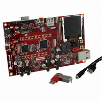
KIT EVAL LPC1768 CR
Manufacturer
NXP Semiconductors
Type
MCUr
Datasheet
1.OM11043.pdf
(79 pages)
Specifications of OM11035
Contents
Board and software
For Use With/related Products
LPC1768
Lead Free Status / RoHS Status
Lead free / RoHS Compliant
Other names
568-4815


NXP Semiconductors
LPC1769_68_67_66_65_64_63
Product data sheet
7.30.1 Reset
7.30 System control
Reset has four sources on the LPC17xx: the RESET pin, the Watchdog reset, power-on
reset (POR), and the BrownOut Detection (BOD) circuit. The RESET pin is a Schmitt
trigger input pin. Assertion of chip Reset by any source, once the operating voltage attains
a usable level, causes the RSTOUT pin to go LOW and starts the wake-up timer (see
description in
until the external Reset is de-asserted, the oscillator is running, a fixed number of clocks
have passed, and the flash controller has completed its initialization. Once reset is
de-asserted, or, in case of a BOD-triggered reset, once the voltage rises above the BOD
threshold, the RSTOUT pin goes HIGH.
When the internal Reset is removed, the processor begins executing at address 0, which
is initially the Reset vector mapped from the Boot Block. At that point, all of the processor
and peripheral registers have been initialized to predetermined values.
Fig 6.
Power distribution
V
DD(REG)(3V3)
Section
All information provided in this document is subject to legal disclaimers.
V
VREFN
DD(3V3)
RTCX1
RTCX2
VREFP
VBAT
V
V
V
DDA
SSA
SS
7.29.5). The wake-up timer ensures that reset remains asserted
Rev. 6.01 — 11 March 2011
LPC17xx
LPC1769/68/67/66/65/64/63
RTC POWER DOMAIN
ADC POWER DOMAIN
MAIN POWER DOMAIN
OSCILLATOR
SELECTOR
to I/O pads
POWER
32 kHz
REGULATOR
32-bit ARM Cortex-M3 microcontroller
ULTRA LOW-POWER
REGULATOR
DAC
ADC
BACKUP REGISTERS
REAL-TIME CLOCK
to core
to memories,
peripherals,
oscillators,
PLLs
002aad978
© NXP B.V. 2011. All rights reserved.
39 of 79
Related parts for OM11035
Image
Part Number
Description
Manufacturer
Datasheet
Request
R

Part Number:
Description:
NXP Semiconductors designed the LPC2420/2460 microcontroller around a 16-bit/32-bitARM7TDMI-S CPU core with real-time debug interfaces that include both JTAG andembedded trace
Manufacturer:
NXP Semiconductors
Datasheet:

Part Number:
Description:
NXP Semiconductors designed the LPC2458 microcontroller around a 16-bit/32-bitARM7TDMI-S CPU core with real-time debug interfaces that include both JTAG andembedded trace
Manufacturer:
NXP Semiconductors
Datasheet:
Part Number:
Description:
NXP Semiconductors designed the LPC2468 microcontroller around a 16-bit/32-bitARM7TDMI-S CPU core with real-time debug interfaces that include both JTAG andembedded trace
Manufacturer:
NXP Semiconductors
Datasheet:
Part Number:
Description:
NXP Semiconductors designed the LPC2470 microcontroller, powered by theARM7TDMI-S core, to be a highly integrated microcontroller for a wide range ofapplications that require advanced communications and high quality graphic displays
Manufacturer:
NXP Semiconductors
Datasheet:
Part Number:
Description:
NXP Semiconductors designed the LPC2478 microcontroller, powered by theARM7TDMI-S core, to be a highly integrated microcontroller for a wide range ofapplications that require advanced communications and high quality graphic displays
Manufacturer:
NXP Semiconductors
Datasheet:
Part Number:
Description:
The Philips Semiconductors XA (eXtended Architecture) family of 16-bit single-chip microcontrollers is powerful enough to easily handle the requirements of high performance embedded applications, yet inexpensive enough to compete in the market for hi
Manufacturer:
NXP Semiconductors
Datasheet:
Part Number:
Description:
The XA-S3 device is a member of Philips Semiconductors? XA(eXtended Architecture) family of high performance 16-bitsingle-chip microcontrollers
Manufacturer:
NXP Semiconductors
Datasheet:

Part Number:
Description:
The NXP BlueStreak LH75401/LH75411 family consists of two low-cost 16/32-bit System-on-Chip (SoC) devices
Manufacturer:
NXP Semiconductors
Datasheet:
Part Number:
Description:
The NXP LPC3130/3131 combine an 180 MHz ARM926EJ-S CPU core, high-speed USB2
Manufacturer:
NXP Semiconductors
Datasheet:
Part Number:
Description:
The NXP LPC3141 combine a 270 MHz ARM926EJ-S CPU core, High-speed USB 2
Manufacturer:
NXP Semiconductors
Part Number:
Description:
The NXP LPC3143 combine a 270 MHz ARM926EJ-S CPU core, High-speed USB 2
Manufacturer:
NXP Semiconductors

Part Number:
Description:
The NXP LPC3152 combines an 180 MHz ARM926EJ-S CPU core, High-speed USB 2
Manufacturer:
NXP Semiconductors
Part Number:
Description:
The NXP LPC3154 combines an 180 MHz ARM926EJ-S CPU core, High-speed USB 2
Manufacturer:
NXP Semiconductors

Part Number:
Description:
Standard level N-channel enhancement mode Field-Effect Transistor (FET) in a plastic package using NXP High-Performance Automotive (HPA) TrenchMOS technology
Manufacturer:
NXP Semiconductors
Datasheet: