MC56F8367EVME Freescale Semiconductor, MC56F8367EVME Datasheet - Page 140
MC56F8367EVME
Manufacturer Part Number
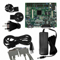
MC56F8367EVME
Description
EVAL BOARD FOR MC56F83X
Manufacturer
Freescale Semiconductor
Type
DSPr
Specifications of MC56F8367EVME
Contents
Module and Misc Hardware
Processor To Be Evaluated
MC56F8145-67 and MC56F8345-67
Data Bus Width
16 bit
Interface Type
RS-232
Silicon Manufacturer
Freescale
Core Architecture
56800/E
Core Sub-architecture
56800/E
Silicon Core Number
MC56F
Silicon Family Name
MC56F83xx
Rohs Compliant
Yes
For Use With/related Products
MC56F83x5, MC56F83x6, MC56F83x7
Lead Free Status / RoHS Status
Lead free / RoHS Compliant


1. Theta-JA determined on 2s2p test boards is frequently lower than would be observed in an application. Determined on 2s2p ther-
2. Junction to ambient thermal resistance, Theta-JA (R
3. Junction to case thermal resistance, Theta-JC (R
4. Thermal Characterization Parameter, Psi-JT (Ψ
5. Junction temperature is a function of on-chip power dissipation, package thermal resistance, mounting site (board) temperature,
6. See
7. TJ = Junction temperature
140
Junction to ambient
Natural convection
Junction to ambient (@1m/sec)
Junction to ambient
Natural convection
Junction to ambient (@1m/sec)
Junction to case
Junction to center of case
I/O pin power dissipation
Power dissipation
Maximum allowed P
mal test board.
in a horizontal configuration in natural convection. Theta-JA was also simulated on a thermal test board with two internal planes
(2s2p, where “s” is the number of signal layers and “p” is the number of planes) per JESD51-6 and JESD51-7. The correct name
for Theta-JA for forced convection or with the non-single layer boards is Theta-JMA.
plate technique with the cold plate temperature used as the "case" temperature. The basic cold plate measurement technique is
described by MIL-STD 883D, Method 1012.1. This is the correct thermal metric to use to calculate thermal performance when
the package is being used with a heat sink.
ter of case as defined in JESD51-2. Ψ
vironments.
ambient temperature, air flow, power dissipation of other components on the board, and board thermal resistance.
TA = Ambient temperature
TBD = numbers will be available late Q4 2005
Part 12.1
ESD for Human Body Model (HBM)
ESD for Machine Model (MM)
ESD for Charge Device Model (CDM)
Characteristic
Table 10-2 56F8367/56F8167 ElectroStatic Discharge (ESD) Protection
for more details on thermal design considerations.
D
Characteristic
Four layer board (2s2p)
Four layer board (2s2p)
Table 10-3 Thermal Characteristics
JT
is a useful value to use to estimate junction temperature in steady-state customer en-
Comments
JT
56F8367 Technical Data, Rev. 8
), is the "resistance" from junction to reference point thermocouple on top cen-
θJC
θJA
), was simulated to be equivalent to the measured values using the cold
) was simulated to be equivalent to the JEDEC specification JESD51-2
2000
Min
200
500
Symbol
P
R
R
(2s2p)
R
(2s2p)
R
R
P
Ψ
DMAX
P
θJMA
θJMA
θJMA
θJA
θJC
JT
I/O
D
160-pin LQFP
Typ
—
—
—
P
Value
38.5
35.4
31.5
8.6
0.8
33
D
(TJ - TA) / R
User-determined
= (I
DD
6
x V
Max
DD
160MAPBGA
—
—
—
θ
+ P
JA
Value
39.90
TBD
TBD
TBD
TBD
46.8
7
I/O
Freescale Semiconductor
)
Unit
°C/W
°C/W
°C/W
°C/W
°C/W
°C/W
Unit
V
V
V
W
W
W
Preliminary
Notes
1, 2
1, 2
4, 5
2
2
3
Related parts for MC56F8367EVME
Image
Part Number
Description
Manufacturer
Datasheet
Request
R

Part Number:
Description:
56f8300 16-bit Digital Signal Controllers
Manufacturer:
Freescale Semiconductor, Inc
Datasheet:
Part Number:
Description:
Manufacturer:
Freescale Semiconductor, Inc
Datasheet:
Part Number:
Description:
Manufacturer:
Freescale Semiconductor, Inc
Datasheet:
Part Number:
Description:
Manufacturer:
Freescale Semiconductor, Inc
Datasheet:
Part Number:
Description:
Manufacturer:
Freescale Semiconductor, Inc
Datasheet:
Part Number:
Description:
Manufacturer:
Freescale Semiconductor, Inc
Datasheet:
Part Number:
Description:
Manufacturer:
Freescale Semiconductor, Inc
Datasheet:
Part Number:
Description:
Manufacturer:
Freescale Semiconductor, Inc
Datasheet:
Part Number:
Description:
Manufacturer:
Freescale Semiconductor, Inc
Datasheet:
Part Number:
Description:
Manufacturer:
Freescale Semiconductor, Inc
Datasheet:
Part Number:
Description:
Manufacturer:
Freescale Semiconductor, Inc
Datasheet:
Part Number:
Description:
Manufacturer:
Freescale Semiconductor, Inc
Datasheet:
Part Number:
Description:
Manufacturer:
Freescale Semiconductor, Inc
Datasheet:
Part Number:
Description:
Manufacturer:
Freescale Semiconductor, Inc
Datasheet:
Part Number:
Description:
Manufacturer:
Freescale Semiconductor, Inc
Datasheet: