MPC566EVB Freescale Semiconductor, MPC566EVB Datasheet - Page 24
MPC566EVB
Manufacturer Part Number
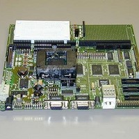
MPC566EVB
Description
KIT EVALUATION FOR MPC565/566
Manufacturer
Freescale Semiconductor
Specifications of MPC566EVB
Processor To Be Evaluated
MPC56x
Data Bus Width
32 bit
Interface Type
RS-232, Ethernet
Lead Free Status / RoHS Status
Contains lead / RoHS non-compliant


Communication Ports
CAN_A, CAN_B, and CAN_C Port Termination Options
The RA1-3, RB1-3, and RC1-3 option locations provide the respective CAN A, B, or C port with
the ability to add bias and/or termination resistance. RA1, RB1, and RC1 locations provide low
bias (to ground) on the respective CAN Port CAN Hi signal. RA3, RB3, and RC3 locations provide
high bias (to +5V) on the respective CAN Port CAN Low signal. RA2, RB2, and RC2 locations
provide termination between the respective CAN Port CAN Hi and CAN Low signals.
1.4.3 10/100T Ethernet Port
The MPC566EVB has an Ethernet controller (SMSC LAN91C111 U20) operating at 10M bits/sec
or 100Mbits/sec (see the device data sheet on the support CD forr operation details). The dBUG
ROM monitor is programmed to allow a user to download files over a network to memory in
different formats. The compiler-formats currently supported are S-Record, COFF, ELF, or Image
(raw binary). Refer to Appendix B, “Configuring dBUG for Network Downloads”, for details on
how to configure the board for network download.
The Ethernet registers are located at chip select CS3 base address in the address range 0x0000 -
0x000F. The access is 16 bits wide or half word transfers only. The LAN91C111 device applies a
register bank selection technique to provide a minimum memory space size. Users should review
the device data sheet in detail for operation notes. The debug monitor applies the Ethernet for file
downloads only, no high level stacks are applied in the sample source code.
RJ45 jack J3 of the Ethernet port provides a direct to HUB type connection. The Ethernet cable
provided with the MPC566EVB kit is a crossover type for direct connection of the EVB to a PC
host network card. If connection to a HUB is desired, a standard Ethernet cable should be applied.
100_IRQ Option Jumper
1-14
Pin 4 = +5V supply for remote use or bias of CAN bus.
Freescale Semiconductor, Inc.
For More Information On This Product,
Table 1-5. Ethernet Jack J3
PIN
1
2
3
4
5
6
7
8
MPC566EVB User’s Manual
Go to: www.freescale.com
SIGNAL
TX+
TX-
RX+
Term 1 75 ohm
Term 1 75 ohm
RX-
Term 2 75 ohm
Term 2 75 ohm
Related parts for MPC566EVB
Image
Part Number
Description
Manufacturer
Datasheet
Request
R

Part Number:
Description:
Manufacturer:
Freescale Semiconductor, Inc
Datasheet:
Part Number:
Description:
Manufacturer:
Freescale Semiconductor, Inc
Datasheet:
Part Number:
Description:
Manufacturer:
Freescale Semiconductor, Inc
Datasheet:
Part Number:
Description:
Manufacturer:
Freescale Semiconductor, Inc
Datasheet:
Part Number:
Description:
Manufacturer:
Freescale Semiconductor, Inc
Datasheet:
Part Number:
Description:
Manufacturer:
Freescale Semiconductor, Inc
Datasheet:
Part Number:
Description:
Manufacturer:
Freescale Semiconductor, Inc
Datasheet:
Part Number:
Description:
Manufacturer:
Freescale Semiconductor, Inc
Datasheet:
Part Number:
Description:
Manufacturer:
Freescale Semiconductor, Inc
Datasheet:
Part Number:
Description:
Manufacturer:
Freescale Semiconductor, Inc
Datasheet:
Part Number:
Description:
Manufacturer:
Freescale Semiconductor, Inc
Datasheet:
Part Number:
Description:
Manufacturer:
Freescale Semiconductor, Inc
Datasheet:
Part Number:
Description:
Manufacturer:
Freescale Semiconductor, Inc
Datasheet:
Part Number:
Description:
Manufacturer:
Freescale Semiconductor, Inc
Datasheet:
Part Number:
Description:
Manufacturer:
Freescale Semiconductor, Inc
Datasheet: