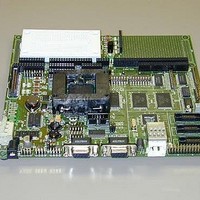
MPC566EVB Freescale Semiconductor, MPC566EVB Datasheet - Page 25

MPC566EVB
Manufacturer Part Number
MPC566EVB
Description
KIT EVALUATION FOR MPC565/566
Manufacturer
Freescale Semiconductor
Specifications of MPC566EVB
Processor To Be Evaluated
MPC56x
Data Bus Width
32 bit
Interface Type
RS-232, Ethernet
Lead Free Status / RoHS Status
Contains lead / RoHS non-compliant
- Current page: 25 of 100
- Download datasheet (2Mb)
The 100_IRQ Option jumper provides Ethernet Interrupt capability to the MPC566 processor.
With the option installed and the LAN91C111 device properly configured, the MPC566 IRQ1
interrupt can be applied to service the port.
LINK and STAT Indicators
The LAN91C111 Ethernet controller provides two indication drivers under software control. The
LINK indicator is driven by the LAN91C111 LEDA output and the STAT indicator is driven by the
LEDB output.
MII Connector
The MII connector location is for testing and the connection of an external Ethernet PHY device.
This connector is not installed or supported by the EVB application.
1.4.4 BDM and NEXUS Development Ports
Both NEXUS (MPC566 Readi Module) and standard BDM (background debug module)
development ports are provided on the MPC566EVB for application of integrated software debug
tool suites. In order to use the BDM, simply connect the 10-pin debug connector on the board,
BDM_PORT, to the P&E BDM wiggler cable provided in the kit. No special setting is needed.
Refer to the MPC566 User’s Manual BDM Section for additiona instructions. The NEXUS
interface provides the IEEE-ISTO 5001 50 pin standard I/O connections and connector and the
BDM port provides the standard 10 pin interface (refer to MPC566EVB schematic sheet 3 for
details). User should observe that both ports can not be applied at the same time. Note that the
NEXUS interface applies some of the MPC566 standard I/O signals from the MIOS module as
alternate development port I/O signals. Following are the I/O effected:
MGPIO 7, 8, 9, 10.
1.4.4.1 BDM Port Options
The BDM Port provides several options for flexibility of operation.
JP3 - BDM Port Interface Level
JP3 provides the option of 2.6V or 3.3V interface levels on the BDM port. This allows the use of
legacy MPC555 BDM tools on the MPC566. The option is set for 3.3V interface from the factory.
The following JP3 reference is with the MPC566EVB setting with the COM ports facing left.
BDM functionality and use is supported via third party developer
software tools. Details may be found on CD-ROM included in this
kit
Freescale Semiconductor, Inc.
For More Information On This Product,
MPC566EVB User’s Manual
Go to: www.freescale.com
NOTE:
Communication Ports
1-15
Related parts for MPC566EVB
Image
Part Number
Description
Manufacturer
Datasheet
Request
R
Part Number:
Description:
Manufacturer:
Freescale Semiconductor, Inc
Datasheet:
Part Number:
Description:
Manufacturer:
Freescale Semiconductor, Inc
Datasheet:
Part Number:
Description:
Manufacturer:
Freescale Semiconductor, Inc
Datasheet:
Part Number:
Description:
Manufacturer:
Freescale Semiconductor, Inc
Datasheet:
Part Number:
Description:
Manufacturer:
Freescale Semiconductor, Inc
Datasheet:
Part Number:
Description:
Manufacturer:
Freescale Semiconductor, Inc
Datasheet:
Part Number:
Description:
Manufacturer:
Freescale Semiconductor, Inc
Datasheet:
Part Number:
Description:
Manufacturer:
Freescale Semiconductor, Inc
Datasheet:
Part Number:
Description:
Manufacturer:
Freescale Semiconductor, Inc
Datasheet:
Part Number:
Description:
Manufacturer:
Freescale Semiconductor, Inc
Datasheet:
Part Number:
Description:
Manufacturer:
Freescale Semiconductor, Inc
Datasheet:
Part Number:
Description:
Manufacturer:
Freescale Semiconductor, Inc
Datasheet:
Part Number:
Description:
Manufacturer:
Freescale Semiconductor, Inc
Datasheet:
Part Number:
Description:
Manufacturer:
Freescale Semiconductor, Inc
Datasheet:
Part Number:
Description:
Manufacturer:
Freescale Semiconductor, Inc
Datasheet:


