MPC566EVB Freescale Semiconductor, MPC566EVB Datasheet - Page 49
MPC566EVB
Manufacturer Part Number
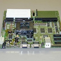
MPC566EVB
Description
KIT EVALUATION FOR MPC565/566
Manufacturer
Freescale Semiconductor
Specifications of MPC566EVB
Processor To Be Evaluated
MPC56x
Data Bus Width
32 bit
Interface Type
RS-232, Ethernet
Lead Free Status / RoHS Status
Contains lead / RoHS non-compliant


configuration options are only presented to the data bus during Hard Reset if enabled by CONFIG
switch position 1. Note that MAP switch also has positions (5 and 8) that are part of the Reset
Configuration Word. All other RCW options can be located on the RW test pads, see RW options
for description of how to apply. The Reset Configuration Word options are all defaulted to logic 0
when the CONFIG Switches are in the OFF position. For more information on the MPC566 Reset
Configuration Word refer to the Reset Chapter in the MPC566 users manual. Five bits are available
on CONFIG_SW (see Table 2-3).I
Notes:
1) Position 1 should be ON at all times until the MPC566 internal flash RCW word is pro-
grammed. This switch will cause the external value RCW to override the internal flash value of
the RCW word.
2) Position 7 and 8 must be enabled for MPC566 internal flash erase or programming operations.
3) All other external RCW bits are provided with the RW hardware options.
RW0 – 30: External Reset Configuration Word (RCW) Options
Switch
1
2
3
4
5
6
7
8
CFG_EN
B0EPEE
Name
CFG1
CFG2
CFG3
CFG4
CFG5
EPEE
MPC565/566
RST_CONF
Function
B0EPEE
COMP1
COMP2
ETRE
EPEE
BDIS
DME
Freescale Semiconductor, Inc.
For More Information On This Product,
Chapter 2. Initialization and Setup
Table 2-3. CONFIG_SW
This switch controls the Exception
This switch enables Compression
This pin enables erasing and pro-
gramming of the internal MPC566
This switch enables programming
or erasing of BLock 0 the internal
Data Bus 3/Boot Dis: This bit en-
enables the external reset config
ables booting from external flash
This switch controls whether Ex-
Go to: www.freescale.com
Enable External Config: This bit
This switch enables Dual Map-
ception vector code is com-
Table Relocation feature
Function
memory
pressed
Mode
flash
flash
ping
MPC566EVB Jumper and Switch Setup
0 = “Decompression ON” mode is dis-
1 = “Decompression ON” mode is en-
0 = MPC566 assumes that the excep-
1 = MPC566 assumes that all excep-
1 = External Reset Config Word se-
0 = Dual Mapping disabled (default)
1 = P/E of Block 0 enabled (default)
0 = Boot from internal memory (de-
0 = Exception table relocation is off
1 = Exception table relocation is on
1 = Internal Flash P/E enabled (de-
0 = Internal Reset Config Word se-
tion routines are non-compressed
0 = Internal Flash P/E disabled
tion routines are compressed
1 = Boot from external flash
1 = Dual Mapping enabled
0 =P/E of Block 0 disabled
lected (default)
abled (default)
(default)
(default)
lected
abled
fault)
fault)
2-9
Related parts for MPC566EVB
Image
Part Number
Description
Manufacturer
Datasheet
Request
R

Part Number:
Description:
Manufacturer:
Freescale Semiconductor, Inc
Datasheet:
Part Number:
Description:
Manufacturer:
Freescale Semiconductor, Inc
Datasheet:
Part Number:
Description:
Manufacturer:
Freescale Semiconductor, Inc
Datasheet:
Part Number:
Description:
Manufacturer:
Freescale Semiconductor, Inc
Datasheet:
Part Number:
Description:
Manufacturer:
Freescale Semiconductor, Inc
Datasheet:
Part Number:
Description:
Manufacturer:
Freescale Semiconductor, Inc
Datasheet:
Part Number:
Description:
Manufacturer:
Freescale Semiconductor, Inc
Datasheet:
Part Number:
Description:
Manufacturer:
Freescale Semiconductor, Inc
Datasheet:
Part Number:
Description:
Manufacturer:
Freescale Semiconductor, Inc
Datasheet:
Part Number:
Description:
Manufacturer:
Freescale Semiconductor, Inc
Datasheet:
Part Number:
Description:
Manufacturer:
Freescale Semiconductor, Inc
Datasheet:
Part Number:
Description:
Manufacturer:
Freescale Semiconductor, Inc
Datasheet:
Part Number:
Description:
Manufacturer:
Freescale Semiconductor, Inc
Datasheet:
Part Number:
Description:
Manufacturer:
Freescale Semiconductor, Inc
Datasheet:
Part Number:
Description:
Manufacturer:
Freescale Semiconductor, Inc
Datasheet: