PM5S-A-24-240V Panasonic Electric Works, PM5S-A-24-240V Datasheet - Page 18
PM5S-A-24-240V
Manufacturer Part Number
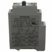
PM5S-A-24-240V
Description
TIMER RELAY ANALOG 24-240V
Manufacturer
Panasonic Electric Works
Series
PM5Sr
Type
Timerr
Specifications of PM5S-A-24-240V
Relay Type
Integrated
Function
Programmable (Multi-Function)
Circuit
DPDT (2 Form C)
Delay Time
0.1 Sec ~ 500 Hrs
Output Type
Mechanical Relay
Contact Rating @ Voltage
5A @ 250VAC
Voltage - Supply
24 ~ 240VAC/DC
Mounting Type
DIN Rail
Termination Style
Screw Terminal
Timing Adjustment Method
Hand Dial
Timing Initiate Method
Input Voltage, Trigger Signal
Lead Free Status / RoHS Status
Lead free / RoHS Compliant
Other names
255-2831
Available stocks
Company
Part Number
Manufacturer
Quantity
Price
Company:

Part Number:
PM5S-A-24-240V
Manufacturer:
Panasonic Electric Works
Quantity:
135


TIMER-RELATED TERMINOLOGY
• What is the timer?
The timer is a relay having such an out-
put (with or without contact) which elec-
trically closes (turns ON) or opens (turns
OFF) the circuit after a preset time elaps-
es when electrical or mechanical input is
given.
• On-delay Operation (Time delay
The on-delay operation is an operation to
give output when preset time expires
after a predetermined input is given to
the power supply circuit or input circuit.
On-delay operation includes power sup-
ply on-delay operation and signal on-
delay operation.
• Off-delay Operation (Time delay
The off-delay operation is an operation to
turn OFF output when preset time
expires after a predetermined input is
given to the power supply circuit or input
circuit, and at the same time output sig-
nal is given and predetermined input is
turned OFF. Off-delay operation
includes power supply off-delay opera-
tion and signal off-delay operation.
• Flicker Operation
The flicker operation is an operation to
repeat output ON/OFF action according
to preset ON time and OFF time while a
predetermined input is given to the
power supply circuit or input circuit.
Flicker operation includes OFF-start flick-
er operation and ON-start flicker opera-
tion.
8
Example of power supply on-delay operation
Power supply
Output signal
( Time delay contact )
Example of OFF-start flicker operation
Power supply
or signal
Output signal
( Time delay contact )
Example of power supply off-delay operation
Power supply
Output signal
( Time delay contact )
operation)
resetting)
ON
ON
ON
ON
Operating time
( In time delay
t
1
operation )
ON
t
2
ON
OFF
Operating time
( In time delay
OFF
t <
t
1
t
t
operation )
t1
1
2
:
:
ON
Output OFF time
Output ON time
t
2
OFF
OFF
OFF
OFF
OFF
t
• Star (
This operation controls the time in the
star connection used for star-delta start-
ing which is conducted for starting a
cage induction motor and the time for
switching the star connection over to
delta connection.
• Preset Time
The preset time is the control time set by
setting time-variable timer.
• Operating Time
The operating time means the time
which elapses between the addition of
predetermined input to the power supply
circuit and input circuit and the comple-
tion of operation for preset time.
• Hold Time
It means the time which elapses
between the completion of operation for
preset time and the start of resetting.
• Pause Time
It means the time elapses between the
start of operation for preset time and the
addition of input required again for the
power supply circuit or input circuit.
Timer does not perform normal function
unless this pause time is set longer than
the timer reset time.
• Resetting
It means that the operation returns to the
state before starting while the timer is in
operation for preset time or after it com-
pletes the operation for preset time.
Resetting during the operation for preset
time is referred to as halfway resetting.
• Reset Time
It means the time elapses between shut-
off of input to the power supply circuit or
input of reset signal and the completion
of resetting.
Timer resetting function shares the reset
of contact, reset of mechanical parts
such as pointer etc., reset of parts in
internal circuit such as capacitor etc.,
and the value at which all of these parts
complete their resetting operation is
regarded as reset time. If timer is used
for a pause time shorter than specified
reset time, the operation time expires
earlier than preset, unexpected instanta-
neous operation takes place or the oper-
ation is failed, thus making it impossible
Power supply
Delta side contact
Star side contact
)/Delta (
ON
t
t
t
1
2
3
:
:
:
ON
Star operation time
-
Delta operation time
t
1
) Operation
Star/Delta switching time
OFF
t
2
ON
t
3
OFF
OFF
to expect the normal operation.
Therefore, be sure to set the timer pause
time longer than the specified reset time.
• Minimum Power Application Time
It means the minimum time during which
power must be supplied in order to oper-
ate timer normally, in the case of power
supply off-delay timer.
• Fluctuation of Operating Time
It means the irregularity in operating time
caused when timer is set at specified
time and the operation is repeated under
the same conditions. It is also referred
to as repetitive error.
• Voltage Error
It means the difference between the
operating time at the rated voltage and
that within the allowable voltage range.
• Temperature Error
It means the difference between the
operating time at the temperature of
20±2°C and that within the allowable
temperature range.
• Set Error
It means the difference between the set
time and the time which actually elapses.
It is also referred to as setting error.
The set error of an analog timer is the
rate to the full-scale value. If the set error
is ±5%, it becomes equivalent to an error
of maximum ±5 hours on the assumption
that 100 hours is set in the range of 100
hours. The error produced when 10
hours is set is also equivalent to an error
of maximum ±5 hours. As far as the set
error is concerned, digital timer is by far
exact. Select a digital timer for the case
when accuracy is required.
When using an analog type multi-range
timer for setting of long time, the setting
procedure stated as follows minimizes
the error. For example, if you want to set
8 hours in the range of 10 hours, first set
the pointer to such a graduation where
the actual operating time should become
as close to 8 seconds as possible in the
range of 10 seconds. Then, reset the
range to 10 hours, leaving the pointer set
at the graduation as it is.
Power supply
( Input signal )
Time delay contact
Internal mechanism
Internal circuit
Power application time
( Input signal
application time )
Operating
time
Hold time
Pause
time
Reset time
Related parts for PM5S-A-24-240V
Image
Part Number
Description
Manufacturer
Datasheet
Request
R


Part Number:
Description:
Manufacturer:
Panasonic Electric Works
Datasheet:
Part Number:
Description:
Manufacturer:
Panasonic Electric Works
Datasheet:

Part Number:
Description:
CONN SOCKET P4 .4MM 50POS SMD
Manufacturer:
Panasonic Electric Works
Datasheet:
Part Number:
Description:
CONN SOCKET .8MM 16POS SMD
Manufacturer:
Panasonic Electric Works
Datasheet:
Part Number:
Description:
CONN HEADER .8MM 16POS SMD
Manufacturer:
Panasonic Electric Works
Datasheet:
Part Number:
Description:
CONN SOCKET .8MM 20POS SMD
Manufacturer:
Panasonic Electric Works
Datasheet:
Part Number:
Description:
CONN SOCKET .8MM 20POS SMD
Manufacturer:
Panasonic Electric Works
Datasheet:
Part Number:
Description:
CONN HEADER .8MM 20POS SMD
Manufacturer:
Panasonic Electric Works
Datasheet:
Part Number:
Description:
CONN SOCKET .8MM 22POS SMD
Manufacturer:
Panasonic Electric Works
Datasheet:
Part Number:
Description:
CONN SOCKET .8MM 30POS SMD
Manufacturer:
Panasonic Electric Works
Datasheet:
Part Number:
Description:
CONN HEADER .8MM 30POS SMD
Manufacturer:
Panasonic Electric Works
Datasheet:
Part Number:
Description:
CONN SOCKET .8MM 30POS SMD
Manufacturer:
Panasonic Electric Works
Datasheet:
Part Number:
Description:
CONN SOCKET .8MM 30POS SMD
Manufacturer:
Panasonic Electric Works
Datasheet:
Part Number:
Description:
CONN HEADER .8MM 30POS SMD
Manufacturer:
Panasonic Electric Works
Datasheet: