PM5S-A-24-240V Panasonic Electric Works, PM5S-A-24-240V Datasheet - Page 8
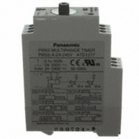
PM5S-A-24-240V
Manufacturer Part Number
PM5S-A-24-240V
Description
TIMER RELAY ANALOG 24-240V
Manufacturer
Panasonic Electric Works
Series
PM5Sr
Type
Timerr
Specifications of PM5S-A-24-240V
Relay Type
Integrated
Function
Programmable (Multi-Function)
Circuit
DPDT (2 Form C)
Delay Time
0.1 Sec ~ 500 Hrs
Output Type
Mechanical Relay
Contact Rating @ Voltage
5A @ 250VAC
Voltage - Supply
24 ~ 240VAC/DC
Mounting Type
DIN Rail
Termination Style
Screw Terminal
Timing Adjustment Method
Hand Dial
Timing Initiate Method
Input Voltage, Trigger Signal
Lead Free Status / RoHS Status
Lead free / RoHS Compliant
Other names
255-2831
Available stocks
Company
Part Number
Manufacturer
Quantity
Price
Company:

Part Number:
PM5S-A-24-240V
Manufacturer:
Panasonic Electric Works
Quantity:
135


Terminal connections
• Refer to the terminal layout and wiring
diagram and securely connect the
terminals accordingly.
• Do not allow control output to exceed
rated control capacity.
1. When one input signal is simultane-
ously applied to more than one timer, be
sure to avoid the wiring shown in Fig. A.
Otherwise, the short-circuit current will
flow and cause damage. Be sure to align
the polarity of the power supply as
shown in Fig. B.
Incorrect
Correct
The PM5S series is provided with a
transformer less power supply system.
Contact or transistor for
external input signal
Short-circuit
current
Contact or transistor for
external input signal
Short-circuit
current
B1
B1
B1
B1
PM5S
PM5S
PM5S
PM5S
A1
A2
A1
A2
A1
A2
A1
A2
Fig. A
Fig. B
Power
supply
Power
supply
2. External surge protection may be
required if the following values are
exceeded. Otherwise, the internal circuit
will be damaged.
Operating voltage
Surge voltage
Surge wave form [±(1.2×50)µs single
polarity full wave voltage]
100
90
50
30
0
0
1.2
Time
Crest value
(µs)
24 to 240 V AC
4,000 V
50
3. For connecting and disconnecting
operating voltage to the timer, a circuit
should be used to prevent the flow of
leakage current. For example, a circuit
for contact protection as shown in Fig. C
will permit leakage current to flow
through R and C, causing erroneous
operation of the timer. Instead, the circuit
shown in Fig. D should be used.
of the timer, long continuous current flow
through the timer, causing generation of
heat internally should be avoided
because of the degradation it can cause.
For such long continuous operation, the
circuit shown below should be used.
4. In order to maintain the characteristics
Power
supply
R: contacts of
relay
No good
Leak current
(Fig. C)
R
R
C
T
PM5S-A/S/M
R
R Relay
Power
supply
T
(Fig. D)
Good
T Time
R
R
C
T
79
Related parts for PM5S-A-24-240V
Image
Part Number
Description
Manufacturer
Datasheet
Request
R


Part Number:
Description:
Manufacturer:
Panasonic Electric Works
Datasheet:
Part Number:
Description:
Manufacturer:
Panasonic Electric Works
Datasheet:

Part Number:
Description:
CONN SOCKET P4 .4MM 50POS SMD
Manufacturer:
Panasonic Electric Works
Datasheet:
Part Number:
Description:
CONN SOCKET .8MM 16POS SMD
Manufacturer:
Panasonic Electric Works
Datasheet:
Part Number:
Description:
CONN HEADER .8MM 16POS SMD
Manufacturer:
Panasonic Electric Works
Datasheet:
Part Number:
Description:
CONN SOCKET .8MM 20POS SMD
Manufacturer:
Panasonic Electric Works
Datasheet:
Part Number:
Description:
CONN SOCKET .8MM 20POS SMD
Manufacturer:
Panasonic Electric Works
Datasheet:
Part Number:
Description:
CONN HEADER .8MM 20POS SMD
Manufacturer:
Panasonic Electric Works
Datasheet:
Part Number:
Description:
CONN SOCKET .8MM 22POS SMD
Manufacturer:
Panasonic Electric Works
Datasheet:
Part Number:
Description:
CONN SOCKET .8MM 30POS SMD
Manufacturer:
Panasonic Electric Works
Datasheet:
Part Number:
Description:
CONN HEADER .8MM 30POS SMD
Manufacturer:
Panasonic Electric Works
Datasheet:
Part Number:
Description:
CONN SOCKET .8MM 30POS SMD
Manufacturer:
Panasonic Electric Works
Datasheet:
Part Number:
Description:
CONN SOCKET .8MM 30POS SMD
Manufacturer:
Panasonic Electric Works
Datasheet:
Part Number:
Description:
CONN HEADER .8MM 30POS SMD
Manufacturer:
Panasonic Electric Works
Datasheet: