PM5S-A-24-240V Panasonic Electric Works, PM5S-A-24-240V Datasheet - Page 19
PM5S-A-24-240V
Manufacturer Part Number
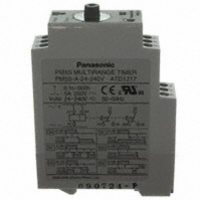
PM5S-A-24-240V
Description
TIMER RELAY ANALOG 24-240V
Manufacturer
Panasonic Electric Works
Series
PM5Sr
Type
Timerr
Specifications of PM5S-A-24-240V
Relay Type
Integrated
Function
Programmable (Multi-Function)
Circuit
DPDT (2 Form C)
Delay Time
0.1 Sec ~ 500 Hrs
Output Type
Mechanical Relay
Contact Rating @ Voltage
5A @ 250VAC
Voltage - Supply
24 ~ 240VAC/DC
Mounting Type
DIN Rail
Termination Style
Screw Terminal
Timing Adjustment Method
Hand Dial
Timing Initiate Method
Input Voltage, Trigger Signal
Lead Free Status / RoHS Status
Lead free / RoHS Compliant
Other names
255-2831
Available stocks
Company
Part Number
Manufacturer
Quantity
Price
Company:

Part Number:
PM5S-A-24-240V
Manufacturer:
Panasonic Electric Works
Quantity:
135


• Pause Time Error
It means the difference between the operating time to a fixed pause time and the operating time to a pause time that varies.
The pause time characteristics are the main characteristics of CR timer (timer exploiting charge and discharge of capacitor C and
resistance R).
If the oscillation count timer (timer which comprises an oscillation circuit composed of CR and quartz and is operated by a counting
circuit inside IC or micro-computer which counts the reference signal) is used, the pause time error becomes almost negligible owing
to its principles of operation. Accordingly, the description about these characteristics may be omitted for the oscillation count timer.
• Equation for Each Error and Measurement Conditions
The operation time shall be measured, in principle, for retention time of 0.5 second and halt time of 1 second.
The measurement shall be repeated five times except for the initial test. The equation for each error and the measurement condi-
tions are shown in the table below:
TM:
Ts:
TMs:
Tmax:
Tmin:
TMx
TMx
TMx
• Functional Vibration Resistance
Means such a vibration as occurs in the
range where the contact closed with that
vibration during the use of the timer
remains closed for the specified time (3
or 1 msec.) minimum.
• Destructive Vibration Resistance
Means such a vibration as occurs in the
range where no part is damage with that
vibration during the transportation or use
of the timer and the operation character-
istics are maintained.
• Functional Shock Resistance
Means such a shock as occurs in the
range where the contact closed with that
shock during the use of the timer
remains closed for the specified time (1
ms) minimum.
• Destructive Shock Resistance
Means such a shock as occurs in the
range where no part is damaged with
that shock during the transportation or
use of the timer and the operation char-
acteristics are maintained.
• Mechanical life
Means the durability that is achieved
when the control output is performed in
the no-load state.
(1) Fluctuation in
(2) Voltage error
(3) Temperature
(4) Set error
(5) Pause time
1
2
3
operation time
error
error
:
:
:
Item
Average of measured values for operation time
Set value
Full-scale value. For digital timers, any arbitrary scale-value may be used.
Maximum of measured values for operation time
Minimum of measured values for operation time
Average of operation time at such voltage as maximizes deviation from TM in allowable voltage range.
Average of operation time at such temperature as maximizes deviation from TM in allowable temperature range.
Average of operation time at such pause time (in the range from the specified reset time to 1 hour) as maximizes deviation from TM.
±
— × ——————— × 100 (%)
1
2
—————— × 100 (%)
—————— × 100 (%)
—————— × 100 (%)
—————— × 100 (%)
TMx
TMx
TMx
TM – Ts
Tmax. – Tmin.
TMs
TMs
TMs
TMs
1
2
3
– TM
– TM
– TM
Equation
TMs
• Electrical life
Means the durability that is achieved
when the specified voltage and current
loads are individually applied to the con-
trol output while being turned ON and
OFF. Generally, the life of the timer is
represented by the number of times the
control output is performed. When a
load is connected to the control output,
the term of "electrical life" is used. When
no load is connected to the control out-
put, the term of "mechanical life" is used.
The electrical life is shorter than the
mechanical life, and becomes longer as
the load decreases. The life of the timer
is made longer by connecting a relay or
a similar part rather than directly switch-
ing a large load with the control output.
• Rated power consumption
Means the power that is consumed when
the rated operation voltage is applied to
the power circuit.
(Rated power consumption = rated volt-
age
• Rated control capacity
Means the reference value that is used
to determine the performance of the
switching part of the load. This value is
represented by the combination of volt-
age and current.
× current consumption)
Set value Ts (Note 1)
Full-scale value
Full-scale value
Note 1: For digital timers, the set value Ts shall be optional.
Note 2: If no question arises from evaluation results, 13-35°C is acceptable.
Note 3: The measurement may be performed in other specified voltage ranges.
Note 4: The measurement may be performed in other specified temperature ranges.
full-scale value
1/3 or more of
TIMER-RELATED TERMINOLOGY
Measurement conditions
power supply (Note 3)
Fluctuation range of
allowable voltage of
Supply voltage
Rated voltage
Rated voltage
• Contact resistance
Means the combined resistance that
consists of the contact resistance
between contacts, and the conductor
resistance of pins and contact springs.
• Insulation resistance
Means the resistance between a contact
or a conductive pin like the pin to which
the operation voltage is applied, and a
dead pin or a non-conductive metallic
part like the time case, the base, or a
retaining screw; or the resistance
between contacts.
• Withstand voltage
Means the limit value that does not
cause breakdown when high voltage is
applied for one minute to the same loca-
tion as measured for insulation resis-
tance. The detectable leak current is
normally 10 mA. In special cases, how-
ever, it may be 1mA or 3 mA.
• Withstand surge voltage
Means the limit value that shows the
durability against momentary abnormal
voltage resulting from lightning or switch-
ing a conductive load. The surge wave-
form is represented by the standard
impulsive voltage waveform at ±(1.2 ×
50) µs or ±(1 × 40) µs.
–10 to 50°C
Ambient temperature
20±2°C
20±2°C
(Note 2)
(Note 4)
(Note 2)
68±36°F
+14 to 122°F
68±36°F
9
Related parts for PM5S-A-24-240V
Image
Part Number
Description
Manufacturer
Datasheet
Request
R


Part Number:
Description:
Manufacturer:
Panasonic Electric Works
Datasheet:
Part Number:
Description:
Manufacturer:
Panasonic Electric Works
Datasheet:

Part Number:
Description:
CONN SOCKET P4 .4MM 50POS SMD
Manufacturer:
Panasonic Electric Works
Datasheet:
Part Number:
Description:
CONN SOCKET .8MM 16POS SMD
Manufacturer:
Panasonic Electric Works
Datasheet:
Part Number:
Description:
CONN HEADER .8MM 16POS SMD
Manufacturer:
Panasonic Electric Works
Datasheet:
Part Number:
Description:
CONN SOCKET .8MM 20POS SMD
Manufacturer:
Panasonic Electric Works
Datasheet:
Part Number:
Description:
CONN SOCKET .8MM 20POS SMD
Manufacturer:
Panasonic Electric Works
Datasheet:
Part Number:
Description:
CONN HEADER .8MM 20POS SMD
Manufacturer:
Panasonic Electric Works
Datasheet:
Part Number:
Description:
CONN SOCKET .8MM 22POS SMD
Manufacturer:
Panasonic Electric Works
Datasheet:
Part Number:
Description:
CONN SOCKET .8MM 30POS SMD
Manufacturer:
Panasonic Electric Works
Datasheet:
Part Number:
Description:
CONN HEADER .8MM 30POS SMD
Manufacturer:
Panasonic Electric Works
Datasheet:
Part Number:
Description:
CONN SOCKET .8MM 30POS SMD
Manufacturer:
Panasonic Electric Works
Datasheet:
Part Number:
Description:
CONN SOCKET .8MM 30POS SMD
Manufacturer:
Panasonic Electric Works
Datasheet:
Part Number:
Description:
CONN HEADER .8MM 30POS SMD
Manufacturer:
Panasonic Electric Works
Datasheet: