PM5S-A-24-240V Panasonic Electric Works, PM5S-A-24-240V Datasheet - Page 21
PM5S-A-24-240V
Manufacturer Part Number
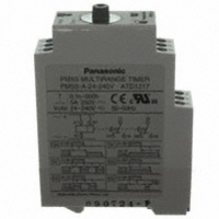
PM5S-A-24-240V
Description
TIMER RELAY ANALOG 24-240V
Manufacturer
Panasonic Electric Works
Series
PM5Sr
Type
Timerr
Specifications of PM5S-A-24-240V
Relay Type
Integrated
Function
Programmable (Multi-Function)
Circuit
DPDT (2 Form C)
Delay Time
0.1 Sec ~ 500 Hrs
Output Type
Mechanical Relay
Contact Rating @ Voltage
5A @ 250VAC
Voltage - Supply
24 ~ 240VAC/DC
Mounting Type
DIN Rail
Termination Style
Screw Terminal
Timing Adjustment Method
Hand Dial
Timing Initiate Method
Input Voltage, Trigger Signal
Lead Free Status / RoHS Status
Lead free / RoHS Compliant
Other names
255-2831
Available stocks
Company
Part Number
Manufacturer
Quantity
Price
Company:

Part Number:
PM5S-A-24-240V
Manufacturer:
Panasonic Electric Works
Quantity:
135


2) If the timer is directly switched with a
non-contact element, leak current may
flow into the timer and cause it to mal-
function.
6. Power off time
If the operation voltage for the timer is
turned ON after the limit time operation is
completed or before the limit time is
reached, the Power off time longer than
the timer restoration time must be
secured.
7. Suicide circuit
If the timer is restored immediately after
the specified time is reached, the circuit
must be configured so that the restora-
tion time of the timer can be secured suf-
ficiently.
If the power circuit for the timer is turned
OFF with the timer contact, a suicide cir-
Cautions for use
(common for all models)
1. Pin connections
Correctly connect the pins while seeing
the terminal layout/wiring diagram. In
particular, the DC type, which has polari-
ties, does not operate with the polarities
connected reverse. Any incorrect con-
nection can cause abnormal heating or
ignition.
2. Connection to operation power supply
1) Supply voltage must be applied at a
time through a switch, a relay, and other
parts. If the voltage is applied gradually,
the specified time may be reached
regardless of its value or the power sup-
ply may not be reset.
2) The operation voltage for the DC type
must be at the specified ripple percent-
age or less. The average voltage must
fall within the allowable operation voltage
range.
Note: Refer to the ripple percentage of each timer.
3) Make sure that no induced voltage
and residual voltage are applied between
the power pins on the timer after the
power switch is turned OFF.
(If the power line is wired in parallel with
the high-voltage and motor lines,
induced voltage may be produced
between the power pins.)
3. Control output
1) The load for the control output must
be used within the load capacity speci-
fied in the rated control capacity. If it is
used exceeding the rated value, the life
is greatly shortened.
Three-phase, half-wave
Single-phase, full-wave
Three-phase, full-wave
Rectification type
Ripple percentage
Approx. 48%
Approx. 17%
Approx. 4%
cuit may be configured (Fig. A). In order
to settle the problem with this potential
suicide circuit, the circuit must be
designed so that the timer is turned OFF
after the self-retention circuit is com-
pletely released (Fig. B).
8. Electrical life
The electrical life varies depending on
the load type, the switching phase, and
the ambient atmosphere. In particular,
the following cases require careful atten-
2) The following connection might result
in short circuit between the heteropolar
contacts in the timer.
4. Installing the timer
1) To install the timer, use the dedicated
pin bracket or socket (cap). Avoid con-
necting the pins on the timer by directly
soldering them.
2) In order to maintain the characteris-
tics, do not remove the timer cover
(case).
5. Superimposed surge of power sup-
ply
For the superimposed surge of power
supply, the standard waveform (±1.2 ×
50µs or ±1 × 40µs) is taken as the stan-
dard value for surge-proof voltage. (The
positive and negative voltages are
applied each three or five times between
the power pins.)
For the standard values for the PM4H,
LT4H and S1DX type timers, see the
respective items in "Cautions for use."
• Single-pole, full-wave voltage for surge
waveform [±(1.2 × 50) µs]
100
90
50
30
Bad example
L
0
1
R
( Fig. A )
0
T
A
L
2
T
PRECAUTIONS IN USING THE TIMERS
1.2
R
Time
Crest value
(µs)
Good example
L
R
( Fig. B )
50
1
T
A
T
L
2
R
tion:
(1) If an AC load is switched in synchro-
nized phases:
Locking or welding is liable to occur due
to contact transposition. Check this with
the actual system.
(2)If a load is switched very frequently:
If a load which generates arcs when a
contact is switched is turned ON and
OFF very frequently, nitrogen and oxy-
gen in air are combined due to arc ener-
gy and then HNO
may corrode metallic materials.
The effective countermeasures include:
1. Using an arc-extinguishing circuit;
2. Decreasing the switching frequency;
and
3. Decreasing the humidity in the ambi-
ent atmosphere.
• Single-pole, full-wave voltage for surge
waveform [±(1 × 40) µs]
• PMH [±(1 × 40) µs]
If external surge occurs exceeding the
specified value, the internal circuit may
break down. In this case, use a surge
absorption element. The typical surge
absorption elements include a varistor, a
capacitor, and a diode. If a surge
absorption element is used, use an oscil-
loscope to see whether or not the foreign
surge exceeding the specified value
appears.
6. Changing the set time
Do not change the set time when the
limit time operation is in progress.
However, this is possible only with the
motor-driven type timer if the set time is
shorter than the remaining time. For
changing the set time on the digital timer
(LT4H series), see the relevant item in
"Cautions for use."
AC type (Except for 24V AC)
12V DC, 24V DC, 24V AC
48V DC
100 to 110V DC
100
90
50
30
0
Voltage type
0
1
Time
3
Crest value
is produced. This
(µs)
40
Surge voltage
4,000V
1,000V
2,000V
500V
11
Related parts for PM5S-A-24-240V
Image
Part Number
Description
Manufacturer
Datasheet
Request
R


Part Number:
Description:
Manufacturer:
Panasonic Electric Works
Datasheet:
Part Number:
Description:
Manufacturer:
Panasonic Electric Works
Datasheet:

Part Number:
Description:
CONN SOCKET P4 .4MM 50POS SMD
Manufacturer:
Panasonic Electric Works
Datasheet:
Part Number:
Description:
CONN SOCKET .8MM 16POS SMD
Manufacturer:
Panasonic Electric Works
Datasheet:
Part Number:
Description:
CONN HEADER .8MM 16POS SMD
Manufacturer:
Panasonic Electric Works
Datasheet:
Part Number:
Description:
CONN SOCKET .8MM 20POS SMD
Manufacturer:
Panasonic Electric Works
Datasheet:
Part Number:
Description:
CONN SOCKET .8MM 20POS SMD
Manufacturer:
Panasonic Electric Works
Datasheet:
Part Number:
Description:
CONN HEADER .8MM 20POS SMD
Manufacturer:
Panasonic Electric Works
Datasheet:
Part Number:
Description:
CONN SOCKET .8MM 22POS SMD
Manufacturer:
Panasonic Electric Works
Datasheet:
Part Number:
Description:
CONN SOCKET .8MM 30POS SMD
Manufacturer:
Panasonic Electric Works
Datasheet:
Part Number:
Description:
CONN HEADER .8MM 30POS SMD
Manufacturer:
Panasonic Electric Works
Datasheet:
Part Number:
Description:
CONN SOCKET .8MM 30POS SMD
Manufacturer:
Panasonic Electric Works
Datasheet:
Part Number:
Description:
CONN SOCKET .8MM 30POS SMD
Manufacturer:
Panasonic Electric Works
Datasheet:
Part Number:
Description:
CONN HEADER .8MM 30POS SMD
Manufacturer:
Panasonic Electric Works
Datasheet: