PM5S-A-24-240V Panasonic Electric Works, PM5S-A-24-240V Datasheet - Page 20
PM5S-A-24-240V
Manufacturer Part Number
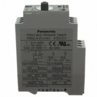
PM5S-A-24-240V
Description
TIMER RELAY ANALOG 24-240V
Manufacturer
Panasonic Electric Works
Series
PM5Sr
Type
Timerr
Specifications of PM5S-A-24-240V
Relay Type
Integrated
Function
Programmable (Multi-Function)
Circuit
DPDT (2 Form C)
Delay Time
0.1 Sec ~ 500 Hrs
Output Type
Mechanical Relay
Contact Rating @ Voltage
5A @ 250VAC
Voltage - Supply
24 ~ 240VAC/DC
Mounting Type
DIN Rail
Termination Style
Screw Terminal
Timing Adjustment Method
Hand Dial
Timing Initiate Method
Input Voltage, Trigger Signal
Lead Free Status / RoHS Status
Lead free / RoHS Compliant
Other names
255-2831
Available stocks
Company
Part Number
Manufacturer
Quantity
Price
Company:

Part Number:
PM5S-A-24-240V
Manufacturer:
Panasonic Electric Works
Quantity:
135


PRECAUTIONS IN USING THE TIMERS
Cautions for circuits
1. Protective circuit for timer contact
In the circuit that switches an inductive load, a contact failure may occur at a contact point due to surge or inrush current resulting
from that switching. Therefore, it is recommended that the following protective circuit be used to protect the contact point.
2. Type of Load and Inrush Current
The type of load and its inrush current
characteristics, together with the switch-
ing frequency are important factors
which cause contact welding.
Particularly for loads with inrush cur-
rents, measure the steady state current
and inrush current and use a relay or
magnet switch which provides an ample
margin of safety. The table below shows
the relationship between typical loads
and their inrush currents.
When you want large load and long life
of the timer, do not control the load direct
with a timer. When the timer is designed
to use a relay or a magnet switch, you
can acquire the longer life of the timer.
3. Connection of input
The PM4H and LT4H series use power
supply without a transformer (power and
input terminals are not insulated). In
connecting various kinds of input signals,
therefore, use a power transformer in
which the primary side is separated from
the ungrounded secondary side as
shown in Fig. A, for the power supply for
a sensor and other input devices so that
short-circuiting can be prevented.
10
Sodium vapor lamp load
Incandescent lamp load 10 to 15 times the steady state current
Application
Device Selection
Features/Notes
Mercury lamp load
Transformer load
Type of load
Capacitive load
Resistive load
Solenoid load
Motor load
Circuit
AC
DC
If the load is a relay or solenoid, the release time lengthens.
Effective when connected to both contacts if the power supply voltage is
24 or 48 V and the voltage across the load is 100 to 200 V.
If the load is a timer, leakage current
flows through the CR circuit causing
faulty operation.
Note: If used with AC voltage, be sure
the impedance of the load is sufficiently
smaller than that of the c and r.
As a guide in selecting r and c,
Values vary depending on the properties of the load and variations in timer character-
istics.
Capacitor c acts to suppress the discharge the moment the contacts open. Resistor r
acts to limit the current when the power is turned on the next time. Test to confirm.
Use a capacitor with a breakdown voltage of 200 to 300 V. Use AC type capacitors
(non-polarized) for AC circuits.
10 to 20 times the steady state current
20 to 40 times the steady state current
5 to 10 times the steady state current
5 to 15 times the steady state current
1 to 3 times the steady state current
1 to 3 times the steady state current
c: 0.5 to 1 µF per 1 A contact current
r: 0.5 to 1 Ω per 1 V contact voltage
Steady state current
Inrush current
Timer contact
(see note.)
Available
r
CR circuit (r: resistor c: capacitor)
c
Do not use a single coil transformer
(e.g., Sly-Duck). Otherwise, the internal
circuit of the timer will be short-circuited
as shown in Fig. B resulting in break-
down.
4. Long Continuous Current Flow
Long continuous current flow through the
timer (approx. one month or longer)
cause generation of heat internally,
which degrade the electronic parts. Use
the timer in combination with a relay and
avoid long continuous current flow
through the timer.
Timer contact
Available
Available
( Fig. A ) Good example
( Fig. B ) Bad example
AC power supply
AC power supply
AC power supply
—
c
r
Insulation transformer
Insulation transformer
Single coil transformer
Timer
Timer
Timer
(+)
(–)
(+)
(–)
(+)
(–)
(–)
(–)
(–)
Alternative
current flow
( e.g. , sensor )
( e.g. , sensor )
( e.g. , sensor )
Input device
Input device
Input device
The diode connected in parallel caus-
es the energy stored in the coil to
flow to the coil in the form of current
and dissipates it as joule heat at the
resistance component of the induc-
tive load.
This circuit further delays the release
time compared to the CR circuit.
(2 to 5 times the release time listed in
the catalog)
Use a diode with a reverse break-
down voltage at least 10 times the
circuit voltage and a forward cur-
rent at least as large as the load
current.
In electronic circuits where the cir-
cuit voltages reverse breakdown
voltage of about 2 to 3 times the
power supply voltage.
Timer contact
Not available
Diode circuit
Available
Diode
(1) When using contact output
(2) When using non-contact output
5. Leakage current
1) For connecting and disconnecting
operating voltage to the timer, a circuit
should be used, which will prevent the
flow of leakage current. For example, a
circuit for contact protection as shown in
Fig A. will permit leakage current flow
through R and C, causing erroneous
operation of the timer. Instead, the cir-
cuit shown in Fig. B should be used.
Operating voltage
Operating voltage
( Fig. A )
( Fig. B )
R
R
Using the rated voltage characteris-
tics of the varistor, this circuit pre-
vents excessively high voltages
from being applied across the con-
tacts. This circuit also slightly
delays the release time.
R
R
Leak current
R
RT
Varistor circuit
Timer contact
T
ZNR varistor
T
Available
Available
R
C
C
R
—
RT
T
R
T
T
Timer
Timer
Related parts for PM5S-A-24-240V
Image
Part Number
Description
Manufacturer
Datasheet
Request
R


Part Number:
Description:
Manufacturer:
Panasonic Electric Works
Datasheet:
Part Number:
Description:
Manufacturer:
Panasonic Electric Works
Datasheet:

Part Number:
Description:
CONN SOCKET P4 .4MM 50POS SMD
Manufacturer:
Panasonic Electric Works
Datasheet:
Part Number:
Description:
CONN SOCKET .8MM 16POS SMD
Manufacturer:
Panasonic Electric Works
Datasheet:
Part Number:
Description:
CONN HEADER .8MM 16POS SMD
Manufacturer:
Panasonic Electric Works
Datasheet:
Part Number:
Description:
CONN SOCKET .8MM 20POS SMD
Manufacturer:
Panasonic Electric Works
Datasheet:
Part Number:
Description:
CONN SOCKET .8MM 20POS SMD
Manufacturer:
Panasonic Electric Works
Datasheet:
Part Number:
Description:
CONN HEADER .8MM 20POS SMD
Manufacturer:
Panasonic Electric Works
Datasheet:
Part Number:
Description:
CONN SOCKET .8MM 22POS SMD
Manufacturer:
Panasonic Electric Works
Datasheet:
Part Number:
Description:
CONN SOCKET .8MM 30POS SMD
Manufacturer:
Panasonic Electric Works
Datasheet:
Part Number:
Description:
CONN HEADER .8MM 30POS SMD
Manufacturer:
Panasonic Electric Works
Datasheet:
Part Number:
Description:
CONN SOCKET .8MM 30POS SMD
Manufacturer:
Panasonic Electric Works
Datasheet:
Part Number:
Description:
CONN SOCKET .8MM 30POS SMD
Manufacturer:
Panasonic Electric Works
Datasheet:
Part Number:
Description:
CONN HEADER .8MM 30POS SMD
Manufacturer:
Panasonic Electric Works
Datasheet: