PM5S-A-24-240V Panasonic Electric Works, PM5S-A-24-240V Datasheet - Page 6
PM5S-A-24-240V
Manufacturer Part Number
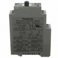
PM5S-A-24-240V
Description
TIMER RELAY ANALOG 24-240V
Manufacturer
Panasonic Electric Works
Series
PM5Sr
Type
Timerr
Specifications of PM5S-A-24-240V
Relay Type
Integrated
Function
Programmable (Multi-Function)
Circuit
DPDT (2 Form C)
Delay Time
0.1 Sec ~ 500 Hrs
Output Type
Mechanical Relay
Contact Rating @ Voltage
5A @ 250VAC
Voltage - Supply
24 ~ 240VAC/DC
Mounting Type
DIN Rail
Termination Style
Screw Terminal
Timing Adjustment Method
Hand Dial
Timing Initiate Method
Input Voltage, Trigger Signal
Lead Free Status / RoHS Status
Lead free / RoHS Compliant
Other names
255-2831
Available stocks
Company
Part Number
Manufacturer
Quantity
Price
Company:

Part Number:
PM5S-A-24-240V
Manufacturer:
Panasonic Electric Works
Quantity:
135


Note: Keep 0.1s or more for power off time.
PM5S-S
Modes and time setting
1) Operation mode setting [PM5S-A]
6 operation modes are selectable with
operation mode selector.
Turn the operation mode selector with
screw driver.
Operation mode is shown up through the
window above the mode selector. The
marks are
the mode selector to the mark until you
can check by clicking sound.
Confirm the mode selector position if it is
correct.
If the position is not stable, the timer
might mis-operate.
Power ON-delay
Operation type
Operation type
One-cycle
Keep 0.05s or more for signal, input time.
OC
ON
,
FL
,
FO
Turn the operation selector to
Timing operation starts when terminals A1 – B1 are connected while
power is ON.
Control output is turned on after the set time, the pulse is 0.5 to 1.0 s.
When power is applied continuously, the time cycle begins. The out-
put contacts change state after the time delay is completed.
,
SF
PM 5S
,
OS
,
OC
. Turn
2) Time setting [common]
16 time ranges are selectable between
1s to 500h.
Turn the time range selector with the
screw driver.
Clockwise turning increases the time
range, and Counter-clockwise turning
decrease the time range.
Confirm the range selector position if it is
correct.
Operation
Operation
OC
.
PM 5S
Power supply
Signal A1-B1
Relay output
(NO contact)
OUT. LED
POWER LED
Power supply
Time-out relay output
(NO contact)
OUT. LED
POWER LED
3) Time setting [common]
To set the time, turn the set dial to a
desired time within the range.
Instantaneous output will be on when the
dial is set to “0”.
When the instantaneous output is used,
the dial should be set under “0” range.
(Instantaneous output area)
When power supply is on, the time
range, setting time and operation mode
cannot be changed.
Turn off the power supply is applied to
set the new operation mode.
To set the time in the range, turn the dial
to a desired time scale. Do not turn the
dial beyond the stopper.
• Cautions for Time setting/Operating
mode setting
1) Time chart
• T shots setting time, t1 and t2 means
the time in setting time. (t1, t2<T)
• When the output relay is turned on, No
contact is closed and NC contact is
opened.
• LED indication
2) Timing operation starts when power is
applied to terminals A1 – B1
Input signal time should be taken over
0.05 sec.
Short-circuited condition: Max. 1kΩ
Open-circuited condition: Min. 100kΩ
ON
ON
Time chart
Time chart
T
T: Setting time
LED lighting
PM5S-A/S/M
shows “Turn ON”
ON
T
T
ON
LED flickering
t
1
0.5-1.0S
77
Related parts for PM5S-A-24-240V
Image
Part Number
Description
Manufacturer
Datasheet
Request
R


Part Number:
Description:
Manufacturer:
Panasonic Electric Works
Datasheet:
Part Number:
Description:
Manufacturer:
Panasonic Electric Works
Datasheet:

Part Number:
Description:
CONN SOCKET P4 .4MM 50POS SMD
Manufacturer:
Panasonic Electric Works
Datasheet:
Part Number:
Description:
CONN SOCKET .8MM 16POS SMD
Manufacturer:
Panasonic Electric Works
Datasheet:
Part Number:
Description:
CONN HEADER .8MM 16POS SMD
Manufacturer:
Panasonic Electric Works
Datasheet:
Part Number:
Description:
CONN SOCKET .8MM 20POS SMD
Manufacturer:
Panasonic Electric Works
Datasheet:
Part Number:
Description:
CONN SOCKET .8MM 20POS SMD
Manufacturer:
Panasonic Electric Works
Datasheet:
Part Number:
Description:
CONN HEADER .8MM 20POS SMD
Manufacturer:
Panasonic Electric Works
Datasheet:
Part Number:
Description:
CONN SOCKET .8MM 22POS SMD
Manufacturer:
Panasonic Electric Works
Datasheet:
Part Number:
Description:
CONN SOCKET .8MM 30POS SMD
Manufacturer:
Panasonic Electric Works
Datasheet:
Part Number:
Description:
CONN HEADER .8MM 30POS SMD
Manufacturer:
Panasonic Electric Works
Datasheet:
Part Number:
Description:
CONN SOCKET .8MM 30POS SMD
Manufacturer:
Panasonic Electric Works
Datasheet:
Part Number:
Description:
CONN SOCKET .8MM 30POS SMD
Manufacturer:
Panasonic Electric Works
Datasheet:
Part Number:
Description:
CONN HEADER .8MM 30POS SMD
Manufacturer:
Panasonic Electric Works
Datasheet: