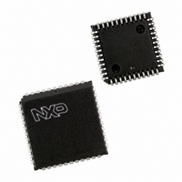
P87C591VFA/00,512 NXP Semiconductors, P87C591VFA/00,512 Datasheet - Page 2

P87C591VFA/00,512
Manufacturer Part Number
P87C591VFA/00,512
Description
IC 80C51 MCU 16K OTP 44-PLCC
Manufacturer
NXP Semiconductors
Series
87Cr
Datasheet
1.P87C591VFA00512.pdf
(160 pages)
Specifications of P87C591VFA/00,512
Core Processor
8051
Core Size
8-Bit
Speed
12MHz
Connectivity
CAN, EBI/EMI, I²C, UART/USART
Peripherals
POR, PWM, WDT
Number Of I /o
32
Program Memory Size
16KB (16K x 8)
Program Memory Type
OTP
Ram Size
512 x 8
Voltage - Supply (vcc/vdd)
4.75 V ~ 5.25 V
Data Converters
A/D 6x10b
Oscillator Type
Internal
Operating Temperature
-40°C ~ 85°C
Package / Case
44-PLCC
Processor Series
P87C5x
Core
80C51
Data Bus Width
8 bit
Data Ram Size
512 B
Interface Type
CAN, I2C, UART
Maximum Clock Frequency
12 MHz
Number Of Programmable I/os
32
Number Of Timers
3
Maximum Operating Temperature
+ 85 C
Mounting Style
SMD/SMT
3rd Party Development Tools
PK51, CA51, A51, ULINK2
Minimum Operating Temperature
- 40 C
On-chip Adc
10 bit, 6 Channel
Lead Free Status / RoHS Status
Lead free / RoHS Compliant
Eeprom Size
-
Lead Free Status / Rohs Status
Details
Other names
568-1256-5
935268182512
P87C591VFAA
935268182512
P87C591VFAA
Available stocks
Company
Part Number
Manufacturer
Quantity
Price
Company:
Part Number:
P87C591VFA/00,512
Manufacturer:
TI
Quantity:
8
Company:
Part Number:
P87C591VFA/00,512
Manufacturer:
NXP Semiconductors
Quantity:
10 000
Philips Semiconductors
CONTENTS
1
1.1
1.2
2
3
4
5
6
6.1
6.2
7
7.1
7.2
7.3
7.4
8
9
10
11
11.1
11.2
11.3
12
12.1
12.2
12.3
12.4
12.5
13
14
14.1
14.2
14.3
14.4
14.5
15
15.1
15.2
15.3
16
16.1
2000 Jul 26
Single-chip 8-bit microcontroller with CAN controller
FEATURES
80C51 Related Features of the 8xC591
CAN Related Features of the 8xC591
GENERAL DESCRIPTION
ORDERING INFORMATION
BLOCK DIAGRAM
FUNCTIONAL DIAGRAM
PINNING INFORMATION
Pinning diagram
Pin description
MEMORY ORGANIZATION
Program Memory
Addressing
Expanded Data RAM addressing
Dual DPTR
I/O FACILITIES
OSCILLATOR CHARACTERISTICS
RESET
LOW POWER MODES
Stop Clock Mode
Idle Mode
Power-down Mode
CAN, CONTROLLER AREA NETWORK
Features of the PeliCAN controller
PeliCAN structure
Communication between PeliCAN controller
and CPU
Register and Message Buffer description
CAN Registers
SERIAL I/O
SIO0 STANDARD SERIAL INTERFACE UART
Multiprocessor Communications
Serial Port Control Register
Baud Rate Generation
More about UART Modes
Enhanced UART
SIO1, I
Modes of Operation
SIO1 Implementation and Operation
Software Examples of SIO1 Service Routines
TIMER 2
Features of Timer 2
2
C SERIAL IO
2
17
18
18.1
18.2
18.3
19
20
20.1
20.2
20.3
20.4
20.5
21
21.1
21.2
21.3
21.4
22
22.1
23
24
25
25.1
26
26.1
26.2
27
28
28.1
29
30
WATCHDOG TIMER (T3)
PULSE WIDTH MODULATED OUTPUTS
Prescaler Frequency Control Register (PWMP)
Pulse Width Register 0 (PWM0)
Pulse Width Register 1 (PWM1)
PORT 1 OPERATION
ANALOG-TO-DIGITAL CONVERTER (ADC)
ADC features
ADC functional description
10-Bit Analog-to-Digital Conversion
10-Bit ADC Resolution and Analog Supply
Power Reduction Modes
INTERRUPTS
Interrupt Enable Registers
Interrupt Enable and Priority Registers
Interrupt priority
Interrupt Vectors
INSTRUCTION SET
Addressing Modes
LIMITING VALUES
DC CHARACTERISTICS
AC CHARACTERISTICS
Timing symbol definitions
EPROM CHARACTERISTICS
Program verification
Security bits
PACKAGE OUTLINES
SOLDERING
Plastic leaded-chip carriers/quad flat-packs
DEFINITIONS
LIFE SUPPORT APPLICATIONS
Preliminary Specification
P8xC591


