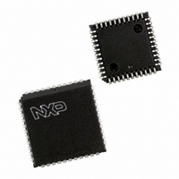
P87C591VFA/00,512 NXP Semiconductors, P87C591VFA/00,512 Datasheet - Page 85

P87C591VFA/00,512
Manufacturer Part Number
P87C591VFA/00,512
Description
IC 80C51 MCU 16K OTP 44-PLCC
Manufacturer
NXP Semiconductors
Series
87Cr
Datasheet
1.P87C591VFA00512.pdf
(160 pages)
Specifications of P87C591VFA/00,512
Core Processor
8051
Core Size
8-Bit
Speed
12MHz
Connectivity
CAN, EBI/EMI, I²C, UART/USART
Peripherals
POR, PWM, WDT
Number Of I /o
32
Program Memory Size
16KB (16K x 8)
Program Memory Type
OTP
Ram Size
512 x 8
Voltage - Supply (vcc/vdd)
4.75 V ~ 5.25 V
Data Converters
A/D 6x10b
Oscillator Type
Internal
Operating Temperature
-40°C ~ 85°C
Package / Case
44-PLCC
Processor Series
P87C5x
Core
80C51
Data Bus Width
8 bit
Data Ram Size
512 B
Interface Type
CAN, I2C, UART
Maximum Clock Frequency
12 MHz
Number Of Programmable I/os
32
Number Of Timers
3
Maximum Operating Temperature
+ 85 C
Mounting Style
SMD/SMT
3rd Party Development Tools
PK51, CA51, A51, ULINK2
Minimum Operating Temperature
- 40 C
On-chip Adc
10 bit, 6 Channel
Lead Free Status / RoHS Status
Lead free / RoHS Compliant
Eeprom Size
-
Lead Free Status / Rohs Status
Details
Other names
568-1256-5
935268182512
P87C591VFAA
935268182512
P87C591VFAA
Available stocks
Company
Part Number
Manufacturer
Quantity
Price
Company:
Part Number:
P87C591VFA/00,512
Manufacturer:
TI
Quantity:
8
Company:
Part Number:
P87C591VFA/00,512
Manufacturer:
NXP Semiconductors
Quantity:
10 000
Philips Semiconductors
15.2.13 T
S1STA is an 8-bit read-only special function register. The
three least significant bits are always zero. The five most
significant bits contain the status code. There are 26
possible status codes. When S1STA contains F8H, no
relevant state information is available and no serial
Table 57 Serial clock rate
Note
1. These frequencies exceed the upper limit of 100 kHz of the standard I
15.2.14 M
The four operating modes are:
Data transfers in each mode of operation are shown in
Figures 37 to 40. These figures contain the following
abbreviations:
2000 Jul 26
Master Transmitter
Master Receiver
Slave Receiver
Slave Transmitter
Abbreviation Explanation
S
SLA
R
W
A
A
Data
P
Single-chip 8-bit microcontroller with CAN controller
CR2
0
0
0
0
1
1
1
1
HE
ORE
CR1
S
0
0
1
1
0
0
1
1
TATUS
I
NFORMATION ON
Start condition
7-bit slave address
Read bit (high level at SDA)
Write bit (low level at SDA)
Acknowledge bit (low level at SDA)
Not acknowledge bit (high level at SDA)
8-bit data byte
Stop condition
R
EGISTER
CR0
0
1
0
1
0
1
0
1
, S1STA
SIO1 O
0.49 > 62.5
0 < 254
6 MHz
12.5
100
200
47
54
63
75
PERATING
BIT FREQUENCY (kHz) at f
M
0.65 < 55.6
ODES
0 < 253
8 MHz
133
267
62.5
83.3
100
71
17
(1)
(1)
85
interrupt is requested. All other S1STA values correspond
to defined SIO1 states. When each of these states is
entered, a serial interrupt is requested (SI = “1”). A valid
status code is present in S1STA one machine cycle after
SI is set by hardware and is still present one machine cycle
after SI has been reset by software.
In Figures 37 to 40, circles are used to indicate when the
serial interrupt flag is set. The numbers in the circles show
the status code held in the S1STA register. At these points,
a service routine must be executed to continue or
complete the serial transfer. These service routines are
not critical since the serial transfer is suspended until the
serial interrupt flag is cleared by software.
When a serial interrupt routine is entered, the status code
in S1STA is used to branch to the appropriate service
routine. For each status code, the required software action
and details of the following serial transfer are given in
Tables 61 to 65.
15.2.14.1 Master Transmitter Mode:
In the master transmitter mode, a number of data bytes are
transmitted to a slave receiver (see Figure 37). Before the
master transmitter mode can be entered, S1CON must be
initialized as in Table 58.
CR0, CR1, and CR2 define the serial bit rate. ENS1 must
be set to logic 1 to enable SIO1. If the AA bit is reset, SIO1
will not acknowledge its own slave address or the general
call address in the event of another device becoming
0.98 < 50.0
CLK
12 MHz
0 < 251
107
125
150
200
400
94
25
2
C-bus specification.
(1)
(1)
(1)
(1)
(1)
48 x (256 (reload value Timer 1))
Reload value Timer 1 in Mode 2.
f
CLK
Preliminary Specification
DIVIDED BY
128
112
480
96
80
60
30
P8xC591


