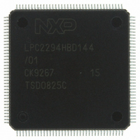
LPC2294HBD144/01,5 NXP Semiconductors, LPC2294HBD144/01,5 Datasheet - Page 11

LPC2294HBD144/01,5
Manufacturer Part Number
LPC2294HBD144/01,5
Description
IC ARM7 MCU FLASH 256K 144-LQFP
Manufacturer
NXP Semiconductors
Series
LPC2200r
Datasheet
1.LPC2292FBD144015.pdf
(53 pages)
Specifications of LPC2294HBD144/01,5
Program Memory Type
FLASH
Program Memory Size
256KB (256K x 8)
Package / Case
144-LQFP
Core Processor
ARM7
Core Size
16/32-Bit
Speed
60MHz
Connectivity
CAN, EBI/EMI, I²C, Microwire, SPI, SSI, SSP, UART/USART
Peripherals
POR, PWM, WDT
Number Of I /o
112
Ram Size
16K x 8
Voltage - Supply (vcc/vdd)
1.65 V ~ 3.6 V
Data Converters
A/D 8x10b
Oscillator Type
Internal
Operating Temperature
-40°C ~ 125°C
Processor Series
LPC22
Core
ARM7TDMI-S
Data Bus Width
16 bit, 32 bit
Data Ram Size
16 KB
Interface Type
CAN/I2C/JTAG/SPI/SSP/UART
Maximum Clock Frequency
60 MHz
Number Of Programmable I/os
112
Number Of Timers
2
Operating Supply Voltage
3.3 V
Maximum Operating Temperature
+ 125 C
Mounting Style
SMD/SMT
3rd Party Development Tools
MDK-ARM, RL-ARM, ULINK2
Development Tools By Supplier
OM10068
Minimum Operating Temperature
- 40 C
On-chip Adc
8-ch x 10-bit
Package
144LQFP
Device Core
ARM7TDMI-S
Family Name
LPC2000
Maximum Speed
60 MHz
Lead Free Status / RoHS Status
Lead free / RoHS Compliant
For Use With
OM10091 - KIT DEV PHYCORE-ARM7/LPC2220622-1005 - USB IN-CIRCUIT PROG ARM7 LPC2K568-1757 - BOARD EVAL FOR LPC220X ARM MCU
Eeprom Size
-
Lead Free Status / Rohs Status
Lead free / RoHS Compliant
Other names
568-4321
935284877551
LPC2294HBD144/01-S
LPC2294HBD144/01-S
935284877551
LPC2294HBD144/01-S
LPC2294HBD144/01-S
Available stocks
Company
Part Number
Manufacturer
Quantity
Price
Company:
Part Number:
LPC2294HBD144/01,5
Manufacturer:
NXP Semiconductors
Quantity:
10 000
NXP Semiconductors
Table 4.
LPC2292_2294_7
Product data sheet
Symbol
P1[25]/EXTIN0
P1[26]/RTCK
P1[27]/TDO
P1[28]/TDI
P1[29]/TCK
P1[30]/TMS
P1[31]/TRST
P2[0] to P2[31]
P2[0]/D0
P2[1]/D1
P2[2]/D2
P2[3]/D3
P2[4]/D4
P2[5]/D5
P2[6]/D6
P2[7]/D7
P2[8]/D8
P2[9]/D9
P2[10]/D10
P2[11]/D11
P2[12]/D12
P2[13]/D13
P2[14]/D14
P2[15]/D15
P2[16]/D16
P2[17]/D17
P2[18]/D18
P2[19]/D19
P2[20]/D20
P2[21]/D21
P2[22]/D22
P2[23]/D23
Pin description
Pin (LQFP)
60
52
144
140
126
113
43
98
105
106
108
109
114
115
116
117
118
120
124
125
127
129
130
131
132
133
134
136
137
1
10
[7]
[7]
[7]
[7]
[7]
[7]
[7]
[7]
[7]
[7]
[7]
[7]
[7]
[7]
[7]
[7]
[7]
[7]
[7]
[7]
[7]
[7]
[7]
[7]
[7]
[7]
[7]
[7]
[7]
[7]
[7]
…continued
Pin
(TFBGA)
K8
N6
B2
A3
A7
D10
M4
E12
C12
C11
B12
A13
C10
B10
A10
D9
C9
A9
A8
B7
C7
A6
B6
C6
D6
A5
B5
D5
A4
A1
E3
[7]
[7]
[7]
[7]
[7]
[7]
[7]
[7]
[7]
[7]
[7]
[7]
[7]
[7]
[7]
[7]
[7]
[7]
[7]
[7]
[7]
[7]
[7]
[7]
[7]
[7]
[7]
[7]
[7]
[7]
[7]
[1]
Type
I
I/O
O
I
I
I
I
I/O
I/O
I/O
I/O
I/O
I/O
I/O
I/O
I/O
I/O
I/O
I/O
I/O
I/O
I/O
I/O
I/O
I/O
I/O
I/O
I/O
I/O
I/O
I/O
I/O
Rev. 7 — 4 December 2008
16/32-bit ARM microcontrollers with external memory interface
Description
EXTIN0 — External Trigger Input. Standard I/O with internal
pull-up.
RTCK — Returned Test Clock output. Extra signal added to
the JTAG port. Assists debugger synchronization when
processor frequency varies. Bidirectional pin with internal
pull-up.
Note: LOW on this pin while RESET is LOW, enables pins
P1[31:26] to operate as Debug port after reset.
TDO — Test Data out for JTAG interface.
TDI — Test Data in for JTAG interface.
TCK — Test Clock for JTAG interface. This clock must be
slower than
to operate.
TMS — Test Mode Select for JTAG interface.
TRST — Test Reset for JTAG interface.
Port 2 — Port 2 is a 32-bit bidirectional I/O port with individual
direction controls for each bit. The operation of port 2 pins
depends upon the pin function selected via the Pin Connect
Block.
D0 — External memory data line 0.
D1 — External memory data line 1.
D2 — External memory data line 2.
D3 — External memory data line 3.
D4 — External memory data line 4.
D5 — External memory data line 5.
D6 — External memory data line 6.
D7 — External memory data line 7.
D8 — External memory data line 8.
D9 — External memory data line 9.
D10 — External memory data line 10.
D11 — External memory data line 11.
D12 — External memory data line 12.
D13 — External memory data line 13.
D14 — External memory data line 14.
D15 — External memory data line 15.
D16 — External memory data line 16.
D17 — External memory data line 17.
D18 — External memory data line 18.
D19 — External memory data line 19.
D20 — External memory data line 20.
D21 — External memory data line 21.
D22 — External memory data line 22.
D23 — External memory data line 23.
1
6
of the CPU clock (CCLK) for the JTAG interface
LPC2292/LPC2294
© NXP B.V. 2008. All rights reserved.
11 of 53


