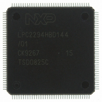
LPC2294HBD144/01,5 NXP Semiconductors, LPC2294HBD144/01,5 Datasheet - Page 23

LPC2294HBD144/01,5
Manufacturer Part Number
LPC2294HBD144/01,5
Description
IC ARM7 MCU FLASH 256K 144-LQFP
Manufacturer
NXP Semiconductors
Series
LPC2200r
Datasheet
1.LPC2292FBD144015.pdf
(53 pages)
Specifications of LPC2294HBD144/01,5
Program Memory Type
FLASH
Program Memory Size
256KB (256K x 8)
Package / Case
144-LQFP
Core Processor
ARM7
Core Size
16/32-Bit
Speed
60MHz
Connectivity
CAN, EBI/EMI, I²C, Microwire, SPI, SSI, SSP, UART/USART
Peripherals
POR, PWM, WDT
Number Of I /o
112
Ram Size
16K x 8
Voltage - Supply (vcc/vdd)
1.65 V ~ 3.6 V
Data Converters
A/D 8x10b
Oscillator Type
Internal
Operating Temperature
-40°C ~ 125°C
Processor Series
LPC22
Core
ARM7TDMI-S
Data Bus Width
16 bit, 32 bit
Data Ram Size
16 KB
Interface Type
CAN/I2C/JTAG/SPI/SSP/UART
Maximum Clock Frequency
60 MHz
Number Of Programmable I/os
112
Number Of Timers
2
Operating Supply Voltage
3.3 V
Maximum Operating Temperature
+ 125 C
Mounting Style
SMD/SMT
3rd Party Development Tools
MDK-ARM, RL-ARM, ULINK2
Development Tools By Supplier
OM10068
Minimum Operating Temperature
- 40 C
On-chip Adc
8-ch x 10-bit
Package
144LQFP
Device Core
ARM7TDMI-S
Family Name
LPC2000
Maximum Speed
60 MHz
Lead Free Status / RoHS Status
Lead free / RoHS Compliant
For Use With
OM10091 - KIT DEV PHYCORE-ARM7/LPC2220622-1005 - USB IN-CIRCUIT PROG ARM7 LPC2K568-1757 - BOARD EVAL FOR LPC220X ARM MCU
Eeprom Size
-
Lead Free Status / Rohs Status
Lead free / RoHS Compliant
Other names
568-4321
935284877551
LPC2294HBD144/01-S
LPC2294HBD144/01-S
935284877551
LPC2294HBD144/01-S
LPC2294HBD144/01-S
Available stocks
Company
Part Number
Manufacturer
Quantity
Price
Company:
Part Number:
LPC2294HBD144/01,5
Manufacturer:
NXP Semiconductors
Quantity:
10 000
NXP Semiconductors
LPC2292_2294_7
Product data sheet
6.15.2 Features available in LPC2292/LPC2294/01 only
6.16.1 Features
6.17.1 Features
6.16 Watchdog timer
6.17 Real-time clock
The LPC2292/LPC2294/01 can count external events on one of the capture inputs if the
external pulse lasts at least one half of the period of the PCLK. In this configuration,
unused capture lines can be selected as regular timer capture inputs, or used as external
interrupts.
The purpose of the watchdog is to reset the microcontroller within a reasonable amount of
time if it enters an erroneous state. When enabled, the watchdog will generate a system
reset if the user program fails to ‘feed’ (or reload) the watchdog within a predetermined
amount of time.
The Real-Time Clock (RTC) is designed to provide a set of counters to measure time
when normal or idle operating mode is selected. The RTC has been designed to use little
power, making it suitable for battery powered systems where the CPU is not running
continuously (Idle mode).
•
•
•
•
•
•
•
•
•
•
•
•
•
Timer can count cycles of either the peripheral clock (PCLK) or an externally supplied
clock.
When counting cycles of an externally supplied clock, only one of the timer’s capture
inputs can be selected as the timer’s clock. The rate of such a clock is limited to
PCLK / 4. Duration of HIGH/LOW levels on the selected CAP input cannot be shorter
than 1 / (2PCLK).
Internally resets chip if not periodically reloaded.
Debug mode.
Enabled by software but requires a hardware reset or a watchdog reset/interrupt to be
disabled.
Incorrect/incomplete feed sequence causes reset/interrupt if enabled.
Flag to indicate watchdog reset.
Programmable 32-bit timer with internal prescaler.
Selectable time period from (T
T
Measures the passage of time to maintain a calendar and clock.
Ultra-low power design to support battery powered systems.
Provides Seconds, Minutes, Hours, Day of Month, Month, Year, Day of Week, and Day
of Year.
Programmable Reference Clock Divider allows adjustment of the RTC to match
various crystal frequencies.
cy(PCLK)
4.
Rev. 7 — 4 December 2008
16/32-bit ARM microcontrollers with external memory interface
cy(PCLK)
256
LPC2292/LPC2294
4) to (T
cy(PCLK)
2
32
© NXP B.V. 2008. All rights reserved.
4) in multiples of
23 of 53


