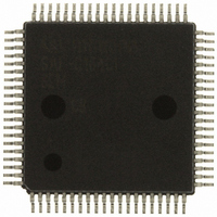
SAF-C164CI-8EM CB Infineon Technologies, SAF-C164CI-8EM CB Datasheet - Page 25

SAF-C164CI-8EM CB
Manufacturer Part Number
SAF-C164CI-8EM CB
Description
IC MCU 16BIT OTP MQFP-80-1
Manufacturer
Infineon Technologies
Series
C16xxr
Datasheet
1.SAF-C164CI-8EM_CB.pdf
(79 pages)
Specifications of SAF-C164CI-8EM CB
Core Processor
C166
Core Size
16-Bit
Speed
20MHz
Connectivity
CAN, EBI/EMI, SPI, SSC, UART/USART
Peripherals
POR, PWM, WDT
Number Of I /o
59
Program Memory Size
64KB (64K x 8)
Program Memory Type
OTP
Ram Size
4K x 8
Voltage - Supply (vcc/vdd)
4.75 V ~ 5.5 V
Data Converters
A/D 8x10b
Oscillator Type
External
Operating Temperature
-40°C ~ 85°C
Package / Case
80-SQFP
Data Bus Width
16 bit
Data Ram Size
4 KB
Interface Type
ASC, CAN, SSC
Maximum Clock Frequency
20 MHz
Number Of Programmable I/os
59
Number Of Timers
3
Maximum Operating Temperature
+ 85 C
Mounting Style
SMD/SMT
Minimum Operating Temperature
- 40 C
On-chip Adc
10 bit, 8 Channel
Packages
PG-MQFP-80
Max Clock Frequency
20.0 MHz
Sram (incl. Cache)
4.0 KByte
Can Nodes
1
A / D Input Lines (incl. Fadc)
8
Program Memory
64.0 KByte
Lead Free Status / RoHS Status
Lead free / RoHS Compliant
Eeprom Size
-
Lead Free Status / Rohs Status
Details
Other names
F164CI8EMCBNT
F164CI8EMCBXT
SAF-C164CI-8EMCB
SAF-C164CI-8EMCBINTR
SAF-C164CI-8EMCBTR
SAF-C164CI-8EMCBTR
SAFC164CI8EMCBXT
SP000103499
F164CI8EMCBXT
SAF-C164CI-8EMCB
SAF-C164CI-8EMCBINTR
SAF-C164CI-8EMCBTR
SAF-C164CI-8EMCBTR
SAFC164CI8EMCBXT
SP000103499
The Capture/Compare Unit CAPCOM6
The CAPCOM6 unit supports generation and control of timing sequences on up to three
16-bit capture/compare channels plus one 10-bit compare channel.
In compare mode the CAPCOM6 unit provides two output signals per channel which
have inverted polarity and non-overlapping pulse transitions. The compare channel can
generate a single PWM output signal and is further used to modulate the capture/
compare output signals.
In capture mode the contents of compare timer 12 is stored in the capture registers upon
a signal transition at pins CCx.
Compare timers T12 (16-bit) and T13 (10-bit) are free running timers which are clocked
by the prescaled CPU clock.
Figure 5
For motor control applications both subunits may generate versatile multichannel PWM
signals which are basically either controlled by compare timer 12 or by a typical hall
sensor pattern at the interrupt inputs (block commutation).
Note: Multichannel signal generation is provided only in devices with a full CAPCOM6.
Data Sheet
The timer registers (T12, T13) are not directly accessible.
The period and offset registers are loading a value into the timer registers.
The shaded blocks are available in the full function module only.
f
f
CPU
CPU
CAPCOM6 Block Diagram
Period Register
Period Register
Control Register
Offset Register
Timer T12
Timer T13
Compare
Compare
T12P
T13P
CTCON
T12OF
16-Bit
10-Bit
Select Register
Compare Register
CC6MSEL
CC Channel 0
CC Channel 1
CC Channel 2
Mode
CMP13
CC60
CC61
CC62
21
Trap Register
CC6MCON.H
Commutation
Control
Control
Block
Logic
Port
CC6POS0
CC6POS1
CC6POS2
CTRAP
CC60
COUT60
CC61
COUT61
CC62
COUT62
COUT63
MCB04109
C164CL/SL
V2.0, 2001-05
C164CI/SI


