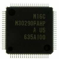
M30290FAHP#U5A Renesas Electronics America, M30290FAHP#U5A Datasheet - Page 492

M30290FAHP#U5A
Manufacturer Part Number
M30290FAHP#U5A
Description
IC M16C/29 MCU FLASH 96K 80LQFP
Manufacturer
Renesas Electronics America
Series
M16C™ M16C/Tiny/29r
Datasheet
1.M30291FCHPU5A.pdf
(501 pages)
Specifications of M30290FAHP#U5A
Core Processor
M16C/60
Core Size
16-Bit
Speed
20MHz
Connectivity
CAN, I²C, IEBus, SIO, UART/USART
Peripherals
DMA, POR, PWM, Voltage Detect, WDT
Number Of I /o
71
Program Memory Size
96KB (96K x 8)
Program Memory Type
FLASH
Ram Size
8K x 8
Voltage - Supply (vcc/vdd)
2.7 V ~ 5.5 V
Data Converters
A/D 27x10b
Oscillator Type
Internal
Operating Temperature
-20°C ~ 85°C
Package / Case
80-LQFP
For Use With
R0K330290S000BE - KIT EVAL STARTER FOR M16C/29M30290T2-CPE - EMULATOR COMPACT M16C/26A/28/29M30290T2-CPE-HP - EMULATOR COMPACT FOR M16C/TINY
Lead Free Status / RoHS Status
Lead free / RoHS Compliant
Eeprom Size
-
Available stocks
Company
Part Number
Manufacturer
Quantity
Price
Part Number:
M30290FAHP#U5AM30290FAHP#D3
Manufacturer:
Renesas Electronics America
Quantity:
10 000
Part Number:
M30290FAHP#U5AM30290FAHP#U3A
Manufacturer:
Renesas Electronics America
Quantity:
135
Part Number:
M30290FAHP#U5AM30290FAHP#U3A
Manufacturer:
Renesas Electronics America
Quantity:
10 000
- Current page: 492 of 501
- Download datasheet (5Mb)
Rev.
Date
REVISION HISTORY
Page
160
166
167
168
170
171
174
175
176
177
180
182
183
184
185
186
187
188
190
192
193
195
196
• Figure 13.21 Prescaler Function and Gate Function Note 1 modified
• Table 13.10 SR Waveform Output Mode Specifications Specification modified
• Figure 13.24 Set/Reset Waveform Output Mode Description for (1) Free-run-
• Table 13.11 Pin Setting for Time Measurement and Waveform Generating
Serial I/O
• Note is modified
• Figure 14.1 Block Diagram of UARTi (i = 0 to 2) PLL clock is added to the
• Figure 14.4 U0TB to U2TB, U0RB to U2RB, U0BRG to U2BRG Registers
• Figure 14.5 U0MR Register, U1MR Register Bit map is modified
• Figure 14.6 U0C0 Register Note 3 modified, Note 4 to 7 are added
• Figure 14.6 U2C0 Register Note 2 is added
• Figure 14.7 PACR Register added
• Table 14.1 Clock Synchronous Serial I/O Mode Specifications Select func-
• Table 14.3 Pin Functions Note 1 added
• Table 14.4 P6
• Figure 14.10 Typical transmit/receive timings in clock synchronous serial I/
• 14.1.1.1 Counter Measre for Communication Error Occurs newly added
• 14.1.1.2 CLK Polarity Select Function Newly added
• Figure 14.14 Transfer Clock Output From Multiple Pins Note 2 added
• 14.1.1.7 CTS/RTS separate function (UART0) modified
• Figure 14.15 CTS/RTS Separate Function Usage Note 1 added
• Table 14.5 UART Mode Specifications Select function modified, note 1 modi-
• Table 14.7 I/O Pin Functions in UART Mode Note 1 added
• Table 14.8 P6
• Figure 14.17 Receive Operation RTSi line is modified
• 14.1.2.1 Bit Rates newly added
• Table 14.9 Example of Bit Rates and Settings newly added
• 14.1.2.2 Counter Measure for Communication Error newly added
• 14.1.2.6 CTS/RTS Separate Function (UART0) P7
• Figure 14.21 CTS/RTS Separate Function Note 1 added
• Table 14.10 I
note 1 is added
upper portion of diagram
ning operation modified, register names modified
Functions Description of port direction modified
tion modified, note 2 modified
O mode Example of receive timing: figure modified
fied
Note 2 is modified, note 3 is newly added
_______ _______
2
4
4
C mode Specifications Note 2 modified
Pin Functions Note 1 added
Pin Functions in UART Mode Note 2 added
C-8
Description
M16C/29 Hardware Manual
Summary
________
0
pin is added
Related parts for M30290FAHP#U5A
Image
Part Number
Description
Manufacturer
Datasheet
Request
R

Part Number:
Description:
KIT STARTER FOR M16C/29
Manufacturer:
Renesas Electronics America
Datasheet:

Part Number:
Description:
KIT STARTER FOR R8C/2D
Manufacturer:
Renesas Electronics America
Datasheet:

Part Number:
Description:
R0K33062P STARTER KIT
Manufacturer:
Renesas Electronics America
Datasheet:

Part Number:
Description:
KIT STARTER FOR R8C/23 E8A
Manufacturer:
Renesas Electronics America
Datasheet:

Part Number:
Description:
KIT STARTER FOR R8C/25
Manufacturer:
Renesas Electronics America
Datasheet:

Part Number:
Description:
KIT STARTER H8S2456 SHARPE DSPLY
Manufacturer:
Renesas Electronics America
Datasheet:

Part Number:
Description:
KIT STARTER FOR R8C38C
Manufacturer:
Renesas Electronics America
Datasheet:

Part Number:
Description:
KIT STARTER FOR R8C35C
Manufacturer:
Renesas Electronics America
Datasheet:

Part Number:
Description:
KIT STARTER FOR R8CL3AC+LCD APPS
Manufacturer:
Renesas Electronics America
Datasheet:

Part Number:
Description:
KIT STARTER FOR RX610
Manufacturer:
Renesas Electronics America
Datasheet:

Part Number:
Description:
KIT STARTER FOR R32C/118
Manufacturer:
Renesas Electronics America
Datasheet:

Part Number:
Description:
KIT DEV RSK-R8C/26-29
Manufacturer:
Renesas Electronics America
Datasheet:

Part Number:
Description:
KIT STARTER FOR SH7124
Manufacturer:
Renesas Electronics America
Datasheet:

Part Number:
Description:
KIT STARTER FOR H8SX/1622
Manufacturer:
Renesas Electronics America
Datasheet:

Part Number:
Description:
KIT DEV FOR SH7203
Manufacturer:
Renesas Electronics America
Datasheet:


