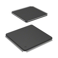
HD6417709SF133B Renesas Electronics America, HD6417709SF133B Datasheet
HD6417709SF133B
Specifications of HD6417709SF133B
Available stocks


Related parts for HD6417709SF133B


HD6417709SF133B Summary of contents
Page 1
To our customers, Old Company Name in Catalogs and Other Documents st On April 1 , 2010, NEC Electronics Corporation merged with Renesas Technology Corporation, and Renesas Electronics Corporation took over all the business of both companies. Therefore, although the ...
Page 2
All information included in this document is current as of the date this document is issued. Such information, however, is subject to change without any prior notice. Before purchasing or using any Renesas Electronics products listed herein, please confirm ...
Page 3
SH7709S Group 32 Hardware Manual Renesas 32-Bit RISC Microcomputer SuperH SH7700 Series The revision list can be viewed directly by clicking the title page. The revision list summarizes the locations of revisions and additions. Details should always be checked by ...
Page 4
...
Page 5
Renesas 32-Bit RISC Microcomputer SuperH RISC engine Family/SH7700 Series SH7709S Group Hardware Manual REJ09B0081-0500O ...
Page 6
Cautions Keep safety first in your circuit designs! 1. Renesas Technology Corp. puts the maximum effort into making semiconductor products better and more reliable, but there is always the possibility that trouble may occur with them. Trouble with semiconductors may ...
Page 7
General Precautions on Handling of Product 1. Treatment of NC Pins Note: Do not connect anything to the NC pins. The NC (not connected) pins are either not connected to any of the internal circuitry or are used as test ...
Page 8
Configuration of This Manual This manual comprises the following items: 1. General Precautions on Handling of Product 2. Configuration of This Manual 3. Preface 4. Contents 5. Overview 6. Description of Functional Modules • CPU and System-Control Modules • On-Chip ...
Page 9
This LSI is a microprocessor with the 32-bit SH-3 CPU as its core and peripheral functions necessary for configuring a user system. This LSI is built in with a variety of peripheral functions such as cache memory, memory management unit ...
Page 10
User manuals for development tools Name of Document C/C++ Compiler, Assembler, Optimizing Linkage Editor User’s Manual Simulator/Debugger User’s Manual Embedded Workshop User’s Manual Rev. 5.00, 09/03, page viii of xliv Document No. ADE-702-246 ADE-702-186 ADE-702-201 ...
Page 11
List of Items Revised or Added for This Version Section Page 1.2 Block Diagram 6 Figure 1.1 Block Diagram 2.5.1 Processor States 53 5.4 Memory-Mapped 113 Cache 5.4.1 Address Array Description ASERAM deleted from figure BRIDGE UDI INTC CPG/WDT External ...
Page 12
Section Page 5.4.3 Examples of 115, Usage 116 6.2.6 Interrupt 127 Exception Handling and Priority Table 6.4 Interrupt Exception Handling Sources and Priority (IRQ Mode) 6.3.6 Interrupt 138 Request Register 0 (IRR0) 8.2.1 Standby Control 184 Register (STBCR) Rev. 5.0, ...
Page 13
Section Page 8.3.3 Precautions 187 when Using the Sleep Mode 8.5.1 Transition to 191 Module Standby Function 9.3 Clock Operating 210 Modes Table 9.4 Available Combinations of Clock Mode and FRQCR Values 9.5.1 Changing the 213 Multiplication Rate 9.8.2 Changing ...
Page 14
Section Page 10.2.13 MCS0 Control 258 Register (MCSCR0) 10.3.4 Synchronous 290 DRAM Interface 10.3.6 PCMCIA 310 Interface Figure 10.32 Basic Timing for PCMCIA Memory Card Interface 10.3.7 Waits between 320 Access Cycles Figure 10.40 Waits between Access Cycles 10.3.10 MCS[0] ...
Page 15
Section Page 16.4 SCIF Interrupts 550 16.5 Usage Notes 551 19.13.2 SC Port Data 610 Register (SCPDR) Description Description amended When the TDFE flag in the serial status register (SCSSR) is set TXI interrupt request is generated. ...
Page 16
Section Page 20.3 Bus Master 622 Interface Figure 20.2 A/D Data Register Access Operation (Reading H'AA40) 23.1 Absolute 657 Maximum Ratings Table 23.1 Absolute Maximum Ratings 23.2 DC 659, Characteristics 662 Table 23.2 DC Characteristics Rev. 5.0, 09/03, page xiv ...
Page 17
Section Page 23.3.6 Synchronous 690 DRAM Timing Figure 23.31 Synchronous DRAM Burst Read Bus Cycle (RAS Down, Same Row Address, CAS Latency = 2) Description Tnop cycle deleted from figure Tc1 Tc2 Tc3/Td1 Tc4/Td2 CKIO t AD A25 to A16 ...
Page 18
Section Page A.2 Pin Specifications 723 Table A.2 Pin Specifications A.3 Treatment of 724 Unused Pins A.4 Pin States in 726 to Access to Each 738 Address Space Table A.3 Pin States (Ordinary Memory/Little Endian) Table A.4 Pin States (Ordinary ...
Page 19
Section 1 Overview and Pin Functions 1.1 SH7709S Features ............................................................................................................. 1.2 Block Diagram .................................................................................................................. 1.3 Pin Description .................................................................................................................. 1.3.1 Pin Assignment .................................................................................................... 1.3.2 Pin Function ......................................................................................................... Section 2 CPU ....................................................................................................................... 19 2.1 Register Configuration ...................................................................................................... 19 2.1.1 Privileged Mode and ...
Page 20
MMU Functions ................................................................................................................ 69 3.4.1 MMU Hardware Management ............................................................................. 69 3.4.2 MMU Software Management............................................................................... 69 3.4.3 MMU Instruction (LDTLB) ................................................................................. 70 3.4.4 Avoiding Synonym Problems............................................................................... 72 3.5 MMU Exceptions .............................................................................................................. 74 3.5.1 TLB Miss Exception ............................................................................................ 74 3.5.2 TLB ...
Page 21
Cache Structure .................................................................................................... 103 5.1.3 Register Configuration ......................................................................................... 105 5.2 Register Description .......................................................................................................... 105 5.2.1 Cache Control Register (CCR) ............................................................................. 105 5.2.2 Cache Control Register 2 (CCR2) ........................................................................ 106 5.3 Cache Operation ................................................................................................................ 109 5.3.1 Searching the Cache ............................................................................................. ...
Page 22
Section 7 User Break Controller 7.1 Overview ........................................................................................................................... 149 7.1.1 Features ................................................................................................................ 149 7.1.2 Block Diagram ..................................................................................................... 150 7.1.3 Register Configuration ......................................................................................... 151 7.2 Register Descriptions......................................................................................................... 152 7.2.1 Break Address Register A (BARA)...................................................................... 152 7.2.2 Break Address Mask Register A ...
Page 23
Transition to Standby Mode ................................................................................. 188 8.4.2 Canceling Standby Mode ..................................................................................... 189 8.4.3 Clock Pause Function........................................................................................... 190 8.5 Module Standby Function ................................................................................................. 191 8.5.1 Transition to Module Standby Function............................................................... 191 8.5.2 Clearing Module Standby Function...................................................................... 191 8.6 Timing of ...
Page 24
Section 10 Bus State Controller (BSC) 10.1 Overview ........................................................................................................................... 223 10.1.1 Features ................................................................................................................ 223 10.1.2 Block Diagram ..................................................................................................... 225 10.1.3 Pin Configuration ................................................................................................. 226 10.1.4 Register Configuration ......................................................................................... 228 10.1.5 Area Overview ..................................................................................................... 229 10.1.6 PCMCIA Support................................................................................................. 232 10.2 BSC ...
Page 25
Features ................................................................................................................ 327 11.1.2 Block Diagram ..................................................................................................... 329 11.1.3 Pin Configuration ................................................................................................. 330 11.1.4 Register Configuration ......................................................................................... 331 11.2 Register Descriptions......................................................................................................... 333 11.2.1 DMA Source Address Registers 0–3 (SAR0–SAR3)........................................... 333 11.2.2 DMA Destination Address Registers 0–3 (DAR0–DAR3) .................................. 334 ...
Page 26
TMU Operation ................................................................................................................. 400 12.3.1 General Operation ................................................................................................ 400 12.3.2 Input Capture Function......................................................................................... 403 12.4 Interrupts ........................................................................................................................... 404 12.4.1 Status Flag Setting Timing ................................................................................... 404 12.4.2 Status Flag Clearing Timing................................................................................. 405 12.4.3 Interrupt Sources and Priorities ............................................................................ 405 12.5 ...
Page 27
Precautions when Using RTC Module Standby ................................................... 426 Section 14 Serial Communication Interface (SCI) 14.1 Overview ........................................................................................................................... 427 14.1.1 Features ................................................................................................................ 427 14.1.2 Block Diagram ..................................................................................................... 428 14.1.3 Pin Configuration ................................................................................................. 431 14.1.4 Register Configuration ......................................................................................... 432 14.2 Register ...
Page 28
Receive Data Timing and Receive Margin in Asynchronous Mode .................... 507 15.4.2 Retransmission (Receive and Transmit Modes) ................................................... 509 Section 16 Serial Communication Interface with FIFO (SCIF) 16.1 Overview ........................................................................................................................... 511 16.1.1 Features ................................................................................................................ 511 16.1.2 Block Diagram ..................................................................................................... ...
Page 29
Port A Control Register (PACR).......................................................................... 570 18.3.2 Port B Control Register (PBCR) .......................................................................... 571 18.3.3 Port C Control Register (PCCR) .......................................................................... 572 18.3.4 Port D Control Register (PDCR) .......................................................................... 573 18.3.5 Port E Control Register (PECR)........................................................................... 574 18.3.6 Port ...
Page 30
Register Description ............................................................................................. 605 19.11.2 Port K Data Register (PKDR) .............................................................................. 606 19.12 Port L................................................................................................................................. 607 19.12.1 Register Description ............................................................................................. 607 19.12.2 Port L Data Register (PLDR) ............................................................................... 608 19.13 SC Port .............................................................................................................................. 609 19.13.1 Register Description ............................................................................................. 609 ...
Page 31
Section 22 User Debugging Interface (UDI) 22.1 Overview ........................................................................................................................... 641 22.2 User Debugging Interface (UDI) ....................................................................................... 641 22.2.1 Pin Descriptions ................................................................................................... 641 22.2.2 Block Diagram ..................................................................................................... 642 22.3 Register Descriptions......................................................................................................... 642 22.3.1 Bypass Register (SDBPR).................................................................................... 643 22.3.2 Instruction Register (SDIR).................................................................................. ...
Page 32
A.3 Treatment of Unused Pins ................................................................................................. 724 A.4 Pin States in Access to Each Address Space ..................................................................... 725 Appendix B Memory-Mapped Control Registers B.1 Register Address Map ....................................................................................................... 739 B.2 Register Bits ...................................................................................................................... 745 Appendix C Product Lineup Appendix D ...
Page 33
Figures Figure 1.1 Block Diagram ..................................................................................................... Figure 1.2 Pin Assignment (FP-208C, FP-208E) .................................................................. Figure 1.3 Pin Assignment (BP-240A).................................................................................. Figure 2.1 User Mode Register Configuration ...................................................................... 20 Figure 2.2 Privileged Mode Register Configuration.............................................................. 21 Figure 2.3 General Registers ................................................................................................. 22 Figure ...
Page 34
Figure 8.3 Manual Reset STATUS Output............................................................................ 193 Figure 8.4 Standby to Interrupt STATUS Output.................................................................. 194 Figure 8.5 Standby to Power-On Reset STATUS Output...................................................... 195 Figure 8.6 Standby to Manual Reset STATUS Output.......................................................... 196 Figure 8.7 Sleep to Interrupt STATUS Output ...
Page 35
Figure 10.28 Synchronous DRAM Mode Write Timing ........................................................... 303 Figure 10.29 Burst ROM Wait Access Timing ......................................................................... 305 Figure 10.30 Burst ROM Basic Access Timing ........................................................................ 306 Figure 10.31 Example of PCMCIA Interface ............................................................................ 308 Figure 10.32 Basic Timing for ...
Page 36
Figure 11.23 Timing Chart of Source Address Reload Function............................................... 373 Figure 11.24 Block Diagram of CMT ....................................................................................... 376 Figure 11.25 Counter Operation ................................................................................................ 380 Figure 11.26 Count Timing ....................................................................................................... 381 Figure 11.27 CMF Setting Timing ............................................................................................ 382 Figure 11.28 Timing ...
Page 37
Figure 14.17 Data Format in Synchronous Communication ..................................................... 474 Figure 14.18 Sample Flowchart for SCI Initialization............................................................... 476 Figure 14.19 Sample Flowchart for Transmitting Serial Data ................................................... 477 Figure 14.20 Example of SCI Transmit Operation .................................................................... 478 Figure 14.21 Sample Flowchart ...
Page 38
Figure 19.8 Port H ................................................................................................................... 601 Figure 19.9 Port J .................................................................................................................... 603 Figure 19.10 Port K ................................................................................................................... 605 Figure 19.11 Port L.................................................................................................................... 607 Figure 19.12 SC Port ................................................................................................................. 609 Figure 20.1 Block Diagram of A/D Converter ........................................................................ 614 Figure 20.2 ...
Page 39
Figure 23.19 Burst ROM Bus Cycle (No Wait) ........................................................................ 678 Figure 23.20 Burst ROM Bus Cycle (Two Waits) .................................................................... 679 Figure 23.21 Burst ROM Bus Cycle (External Wait, WAITSEL = 1) ...................................... 680 Figure 23.22 Synchronous DRAM Read Bus Cycle ...
Page 40
Figure 23.47 TCLK Input Timing ............................................................................................. 707 Figure 23.48 TCLK Clock Input Timing................................................................................... 707 Figure 23.49 Oscillation Settling Time at RTC Crystal Oscillator Power-on............................ 707 Figure 23.50 SCK Input Clock Timing ..................................................................................... 707 Figure 23.51 SCI I/O Timing in Clock ...
Page 41
Tables Table 1.1 SH7709S Features .................................................................................................. Table 1.2 Characteristics......................................................................................................... Table 1.3 SH7709S Pin Function ........................................................................................... Table 2.1 Initial Register Values ............................................................................................ 22 Table 2.2 Addressing Modes and Effective Addresses........................................................... 28 Table 2.3 Instruction Formats ................................................................................................. 32 Table 2.4 Classification of ...
Page 42
Table 8.2 Pin Configuration.................................................................................................... 183 Table 8.3 Register Configuration............................................................................................ 183 Table 8.4 Register States in Standby Mode ............................................................................ 188 Table 9.1 CPG Pins and Functions ......................................................................................... 206 Table 9.2 CPG Register .......................................................................................................... 206 Table 9.3 Clock Operating Modes .......................................................................................... 207 ...
Page 43
Table 13.2 RTC Registers......................................................................................................... 410 Table 13.3 Day-of-Week Codes (RWKCNT) .......................................................................... 413 Table 13.4 Day-of-Week Codes (RWKAR) ............................................................................. 417 Table 13.5 Recommended Oscillator Circuit Constants (Recommended Values).................... 425 Table 14.1 SCI Pins ................................................................................................................. 431 Table 14.2 SCI Registers .......................................................................................................... 432 ...
Page 44
Table 19.1 Port A Register ....................................................................................................... 587 Table 19.2 Port A Data Register (PADR) Read/Write Operations ........................................... 588 Table 19.3 Port B Register........................................................................................................ 589 Table 19.4 Port B Data Register (PBDR) Read/Write Operations ........................................... 590 Table 19.5 Port C Register........................................................................................................ ...
Page 45
Table 23.8 Peripheral Module Signal Timing........................................................................... 706 Table 23.9 UDI-Related Pin Timing......................................................................................... 709 Table 23.10 A/D Converter Characteristics................................................................................ 713 Table 23.11 D/A Converter Characteristics................................................................................ 713 Table A.1 Pin States during Resets, Power-Down States, and Bus-Released State................. 715 Table A.2 Pin ...
Page 46
Rev. 5.00, 09/03, page xliv of xliv ...
Page 47
Section 1 Overview and Pin Functions 1.1 SH7709S Features This LSI is a single-chip RISC microprocessor that integrates a Renesas Technology-original TM RISC-type SuperH architecture CPU as its core that has an on-chip multiplier, cache memory, and a memory management ...
Page 48
Table 1.1 SH7709S Features Item Features CPU Original Renesas Technology SuperH architecture Object code level with SH-1, SH-2, and SH-3 Series 32-bit internal data bus General-register files Sixteen 32-bit general registers (eight 32-bit shadow registers) Eight 32-bit control registers Four ...
Page 49
Item Features Cache memory 16-kbyte cache, mixed instruction/data 256 entries, 4-way set associative, 16-byte block length Write-back, write-through, LRU replacement algorithm 1-stage write-back buffer Maximum 2 ways of the cache can be locked Interrupt 23 external interrupt pins (NMI, IRQ5–IRQ0, ...
Page 50
... MHz 1.8–0.15 V 1.7+0.25 V 100 MHz 1.7–0.15 V Package HD6417709SHF200B 208-pin plastic HQFP (FP-208E) HD6417709SF167B 208-pin plastic LQFP (FP-208C) HD6417709SBP167B 240-pin CSP (BP-240A) HD6417709SF133B 208-pin plastic LQFP (FP-208C) HD6417709SBP133B 240-pin CSP (BP-240A) HD6417709SF100B 208-pin plastic LQFP (FP-208C) HD6417709SBP100B 240-pin CSP (BP-240A) ...
Page 51
Table 1.2 Characteristics Item Characteristics Power supply voltage Operating frequency Process Note: * 2.0 (+0.15, –0.1) V when an IRL or IRLS interrupt is used. I/O: 3.3 ±0.3 V Internal: 2.0 ±0.15 V (200 MHz model 1.9±0.15 V ...
Page 52
Block Diagram MMU TLB CCN CACHE BRIDGE UDI INTC CPG/WDT External bus interface Legend: ADC: A/D converter AUD: Advanced user debugger BSC: Bus state controller CACHE: Cache memory CCN: Cache memory controller CMT: Compare match timer CPG/WDT: Clock pulse ...
Page 53
Pin Description 1.3.1 Pin Assignment STATUS0/PTJ[6] 157 STATUS1/PTJ[7] 158 TCLK/PTH[7] 159 IRQOUT 160 V Q 161 SS CKIO 162 V Q 163 CC TxD0/SCPT[0] 164 SCK0/SCPT[1] 165 TxD1/SCPT[2] 166 SCK1/SCPT[3] 167 TxD2/SCPT[4] 168 SCK2/SCPT[5] 169 RTS2/SCPT[6] 170 RxD0/SCPT[0] 171 ...
Page 54
Note: The pin area enclosed in broken lines is an inner ...
Page 55
Pin Function Table 1.3 SH7709S Pin Function Number of Pins FP-208C FP-208E BP-240A Pin Name 1 D2 MD1 2 C2 MD2 Vcc-RTC * XTAL2 5 D3 EXTAL2 Vss-RTC * NMI 8 ...
Page 56
Number of Pins FP-208C FP-208E BP-240A Pin Name 27 K3 Vss — K4 Vss 28 K1 D19/PTA[ Vcc — L4 Vcc 30 L2 D18/PTA[ D17/PTA[ D16/PTA[ VssQ 34 M2 D15 35 M1 ...
Page 57
Number of Pins FP-208C FP-208E BP-240A Pin Name 57 U4 VssQ VccQ A10 66 W7 A11 67 V7 ...
Page 58
Number of Pins FP-208C FP-208E BP-240A Pin Name BS/PTK[4] 87 W12 RD 88 T13 WE0/DQMLL 89 U13 WE1/DQMLU/WE 90 V13 WE2/DQMUL/ICIORD/ 91 W13 PTK[6] WE3/DQMUU/ICIOWR/ 92 T14 PTK[7] 93 U14 RD/WR AUDSYNC/PTE[7] 94 V14 95 W14 VssQ CS0/MCS[0] 96 T15 ...
Page 59
Number of Pins FP-208C FP-208E BP-240A Pin Name RAS3L/PTJ[0] 106 U18 107 U19 PTJ[1] CASL/PTJ[2] 108 R18 109 T19 VssQ CASU/PTJ[3] 110 T17 111 R19 VccQ 112 U17 PTJ[4] 113 R17 PTJ[5] 114 R16 DACK0/PTD[5] 115 P19 DACK1/PTD[7] 116 P18 ...
Page 60
Number of Pins FP-208C FP-208E BP-240A Pin Name 130 L17 AUDATA[3]/PTG[3] 131 K18 AUDATA[2]/PTG[2] 132 K17 Vss — K16 Vss 133 K19 AUDATA[1]/PTG[1] 134 J17 Vcc — J16 Vcc 135 J18 AUDATA[0]/PTG[0] TRST/PTF[7]/PINT[15] 136 J19 137 H16 TMS/PTF[6]/PINT[14] 138 H17 ...
Page 61
Number of Pins FP-208C FP-208E BP-240A Pin Name — D19 Vss 154 E18 Vcc — C19 Vcc 155 C18 XTAL 156 D18 EXTAL 157 B16 STATUS0/PTJ[6] 158 B17 STATUS1/PTJ[7] 159 B15 TCLK/PTH[7] IRQOUT 160 A16 161 C16 VssQ 162 A15 ...
Page 62
Number of Pins FP-208C FP-208E BP-240A Pin Name CTS2/IRQ5/SCPT[7] 176 A11 MCS[7]/PTC[7]/PINT[7] 177 B11 MCS[6]/PTC[6]/PINT[6] 178 D11 MCS[5]/PTC[5]/PINT[5] 179 C11 MCS[4]/PTC[4]/PINT[4] 180 B10 181 C10 VssQ WAKEUP/PTD[3] 182 D10 183 A10 VccQ RESETOUT/PTD[2] 184 C9 MCS[3]/PTC[3]/PINT[3] 185 D9 MCS[2]/PTC[2]/PINT[2] 186 ...
Page 63
Number of Pins FP-208C FP-208E BP-240A Pin Name 198 B6 AVss 199 A6 AN[0]/PTL[0] 200 D5 AN[1]/PTL[1] 201 C5 AN[2]/PTL[2] 202 D4 AN[3]/PTL[3] 203 A5 AN[4]/PTL[4] 204 C4 AN[5]/PTL[5] 205 A4 AVcc 206 B5 AN[6]/DA[1]/PTL[6] 207 B3 AN[7]/DA[0]/PTL[7] 208 B4 ...
Page 64
Rev. 5.00, 09/03, page 18 of 760 ...
Page 65
Register Configuration 2.1.1 Privileged Mode and Banks Processor Modes: There are two processor modes: user mode and privileged mode. The SH7709S normally operates in user mode, and enters privileged mode when an exception occurs or an interrupt is accepted. ...
Page 66
Notes functions as an index register in the indexed register-indirect addressing mode and indexed GBR-indirect addressing mode. 2. Banked register. Figure 2.1 User Mode Register Configuration Rev. 5.00, 09/03, page 20 of 760 ...
Page 67
R0_BANK1 *2 R1_BANK1 *2 R2_BANK1 *2 R3_BANK1 *2 R4_BANK1 *2 R5_BANK1 *2 R6_BANK1 *2 R7_BANK1 R8 R9 R10 R11 R12 R13 R14 R15 SR SSR GBR MACH MACL PR VBR PC SPC *1 *3 R0_BANK0 ...
Page 68
Register values after a reset are shown in table 2.1. Table 2.1 Initial Register Values Type General registers Control registers System registers Note: * Register values are initialized at power-on reset or manual reset. 2.1.2 General Registers There are 16 ...
Page 69
System Registers System registers can be accessed by the LDS and STS instructions. When an exception occurs, the contents of the program counter (PC) are saved in the saved program counter (SPC). The SPC contents are restored to the ...
Page 70
SSR 31 SPC 31 GBR 31 VBR MD: Processor operation mode bit: Indicates the processor operation mode as follows: MD =1: Privileged mode User mode MD ...
Page 71
Data Formats 2.2.1 Data Format in Registers Register operands are always longwords (32 bits, figure 2.6). When a memory operand is only a byte (8 bits word (16 bits sign-extended into a longword when loaded ...
Page 72
Instruction Features 2.3.1 Execution Environment Data Length: The SH7709S instruction set is implemented with fixed-length 16-bit wide instructions executed in a pipelined sequence with single-cycle execution for most instructions. All operations are executed in 32-bit longword units. Memory can ...
Page 73
T bit: The T bit in the status register (SR) is used to indicate the result of compare operations, and is read as a TRUE/FALSE condition determining if a conditional branch is taken or not. To improve processing speed, the ...
Page 74
Addressing Modes Addressing modes and effective address calculation methods are shown in table 2.2. Table 2.2 Addressing Modes and Effective Addresses Addressing Instruction Mode Format Effective Address Calculation Method Register direct Rn Effective address is register Rn. (Operand is ...
Page 75
Addressing Instruction Mode Format Effective Address Calculation Method Register @(disp:4, Effective address is register Rn contents with indirect with Rn) 4-bit displacement disp added. After disp is displacement zero-extended multiplied by 1 (byte), 2 (word (longword), ...
Page 76
Addressing Instruction Mode Format Effective Address Calculation Method PC-relative @(disp:8, Effective address is register PC contents with PC) with 8-bit displacement disp added. After displacement disp is zero-extended multiplied by 2 (word (longword), according to the ...
Page 77
Addressing Instruction Mode Format Effective Address Calculation Method PC-relative Rn Effective address is sum of register PC and Rn contents. Immediate #imm:8 8-bit immediate data imm of TST, AND, OR, or XOR instruction is zero-extended. #imm:8 8-bit immediate data imm ...
Page 78
Instruction Formats Table 2.3 explains the meaning of instruction formats and source and destination operands. The meaning of the operands depends on the operation code. The following symbols are used. xxxx: Operation code mmmm: Source register nnnn: Destination register ...
Page 79
Instruction Format nm format 15 xxxx nnnn mmmm md format 15 xxxx xxxx mmmm nd4 format 15 xxxx xxxx Source Operand mmmm: register 0 direct xxxx mmmm: register indirect mmmm: register indirect with post- increment (multiply-and- accumulate operation) nnnn: * ...
Page 80
Instruction Format nmd 15 format xxxx nnnn mmmm d format 15 xxxx xxxx d12 format 15 xxxx dddd nd8 format 15 xxxx nnnn i format 15 xxxx xxxx ni format 15 xxxx nnnn Note multiply-and-accumulate instruction, nnnn ...
Page 81
Instruction Set 2.4.1 Instruction Set Classified by Function The SH7709S instruction set includes 68 basic instruction types, as listed in table 2.4. Table 2.4 Classification of Instructions Operation Classification Types Code Data transfer 5 MOV MOVA MOVT SWAP XTRCT ...
Page 82
Operation Classification Types Code Arithmetic 21 MUL operations (cont) MULS MULU NEG NEGC SUB SUBC SUBV Logic 6 AND operations NOT OR TAS TST XOR Shift 12 ROTL ROTR ROTCL ROTCR SHAL SHAR SHLL SHLLn SHLR SHLRn SHAD SHLD Rev. ...
Page 83
Operation Classification Types Code Branch BRA BRAF BSR BSRF JMP JSR RTS System 15 CLRMAC control CLRT CLRS LDC LDS LDTLB NOP PREF RTE SETS SETT SLEEP STC STS TRAPA Total: 68 Function Conditional branch, delayed conditional ...
Page 84
Table 2.5 lists the SH7709S instruction code formats. Table 2.5 Instruction Code Format Item Format Instruction OP.Sz SRC,DEST mnemonic Instruction MSB LSB code Operation , summary (xx) M/Q/T & <<n, >>n Privileged mode Execution cycles T bit ...
Page 85
Table 2.6 lists the SH7709S data transfer instructions Table 2.6 Data Transfer Instructions Instruction Operation imm MOV #imm,Rn (disp MOV.W @(disp,PC),Rn extension (disp MOV.L @(disp,PC),Rn Rm MOV Rm,Rn Rm MOV.B Rm,@Rn Rm MOV.W Rm,@Rn Rm MOV.L Rm,@Rn (Rm) MOV.B @Rm,Rn ...
Page 86
Instruction Operation Rm MOV.W Rm,@(R0,Rn) Rm MOV.L Rm,@(R0,Rn) (R0 + Rm) MOV.B @(R0,Rm),Rn extension (R0 + Rm) MOV.W @(R0,Rm),Rn extension (R0 + Rm) MOV.L @(R0,Rm),Rn R0,@(disp,GBR) R0 MOV.B R0,@(disp,GBR) R0 MOV.W R0,@(disp,GBR) R0 MOV.L @(disp,GBR),R0 (disp + GBR) MOV.B extension ...
Page 87
Table 2.7 lists the SH7709S arithmetic instructions. Table 2.7 Arithmetic Instructions Instruction Operation ADD Rm, imm ADD #imm, ADDC Rm,Rn Carry ADDV Rm,Rn Overflow If R0 imm, ...
Page 88
Instruction Operation Signed operation of DMULS.L Rm, MACL 32 Unsigned operation of DMULU.L Rm, MACL 32 Rn – else 0 A byte sign- EXTS.B Rm,Rn extended A ...
Page 89
Instruction Operation 0–Rm NEG Rm,Rn 0–Rm–T NEGC Rm,Rn Borrow Rn–Rm SUB Rm,Rn Rn–Rm–T SUBC Rm,Rn Borrow Rn–Rm SUBV Rm,Rn Underflow Note: * The normal number of execution cycles is shown. The value in parentheses is the number of cycles required ...
Page 90
Table 2.8 lists the SH7709S logic operation instructions. Table 2.8 Logic Operation Instructions Instruction Operation Rn & Rm AND Rm,Rn R0 & imm AND #imm,R0 (R0 + GBR) & imm AND.B #imm,@(R0,GBR) (R0 + GBR) ~Rm NOT Rm, ...
Page 91
Table 2.9 lists the SH7709S shift instructions. Table 2.9 Shift Instructions Instruction Operation T Rn ROTL Rn LSB ROTR ROTCL ROTCR << Rm SHAD Rm,Rn Rn < >> ...
Page 92
Table 2.10 lists the SH7709S branch instructions. Table 2.10 Branch Instructions Instruction Operation disp BF label nop Delayed branch BF/S label disp nop ...
Page 93
Table 2.11 lists the SH7709S system control instructions. Table 2.11 System Control Instructions Instruction Operation 0 MACH, MACL CLRMAC 0 S CLRS 0 T CLRT Rm SR LDC Rm,SR Rm GBR LDC Rm,GBR Rm VBR LDC Rm,VBR Rm SSR LDC ...
Page 94
Instruction Operation (Rm) LDC.L @Rm R6_BANK (Rm) LDC.L @Rm R7_BANK Rm MACH LDS Rm,MACH Rm MACL LDS Rm,MACL Rm PR LDS Rm,PR (Rm) LDS.L @Rm+,MACH (Rm) LDS.L @Rm+,MACL (Rm) LDS.L @Rm+,PR PTEH/PTEL LDTLB No ...
Page 95
Instruction Operation Rn–4 STC.L SSR,@–Rn Rn–4 STC.L SPC,@–Rn Rn–4 STC.L R0_BANK, @–Rn Rn–4 STC.L R1_BANK, @–Rn Rn–4 STC.L R2_BANK, @–Rn Rn–4 STC.L R3_BANK, @–Rn Rn–4 STC.L R4_BANK, @–Rn Rn–4 STC.L R5_BANK, @–Rn Rn–4 STC.L R6_BANK, @–Rn Rn–4 STC.L R7_BANK, @–Rn ...
Page 96
Instruction Code Map Table 2.12 shows the instruction code map. Table 2.12 Instruction Code Map Instruction Code Fx: 0000 MD: 00 MSB LSB 0000 Rn Fx 0000 0000 Rn Fx 0001 0000 Rn 00MD 0010 STC SR,Rn 0000 Rn ...
Page 97
Instruction Code Fx: 0000 MD: 00 MSB LSB 0100 Rn Fx 0000 SHLL Rn 0100 Rn Fx 0001 SHLR Rn 0100 Rn Fx 0010 STS.L MACH,@-Rn 0100 Rn 00MD 0011 STC.L SR,@-Rn 0100 Rn 01MD 0011 STC.L SPC,@-Rn 0100 Rn ...
Page 98
Instruction Code Fx: 0000 MD: 00 MSB LSB 1000 00MD Rn disp MOV.B R0,@(disp:4,Rn) 1000 01MD Rm disp MOV.B @(disp:4,Rm),R0 1000 10MD imm/disp CMP/EQ #imm:8,R0 1000 11MD imm/disp 1001 Rn disp MOV.W @(DISP:8,PC),RN 1010 disp BRA label:12 1011 disp BSR ...
Page 99
Processor States and Processor Modes 2.5.1 Processor States The SH7709S has five processor states: the reset state, exception-handling state, bus-released state, program execution state, and power-down state. Reset State: In this state the CPU is reset. The CPU enters ...
Page 100
From any state when RESETP = 0 Power-on reset Interrupt Bus-released state Bus Bus request request clearance Sleep mode CA = 1,RESETP=0 Note: * The hardware standby mode is entered when the CA pin goes low from any state. Figure ...
Page 101
Section 3 Memory Management Unit (MMU) 3.1 Overview 3.1.1 Features The SH7709S has an on-chip memory management unit (MMU) that implements address translation. The SH7709S features a resident translation look-aside buffer (TLB) that caches information for user-created address translation tables ...
Page 102
MMU will generate an exception, change the physical memory mapping, and record the new address translation information. Although the functions of the MMU could also be implemented by software alone, the need for translation to be performed by ...
Page 103
Process 1 Physical memory Process 1 Process 1 Process 2 Process 3 Figure 3.1 MMU Functions Virtual memory Process 1 Physical memory (1) Virtual Process 1 memory Physical memory Process 2 Process 3 (3) Rev. 5.00, 09/03, page 57 of ...
Page 104
SH7709S MMU Virtual Address Space: The SH7709S uses 32-bit virtual addresses to access a 4-Gbyte virtual address space that is divided into several areas. Address space mapping is shown in figure 3.2. Privileged Mode In privileged mode, there are ...
Page 105
H'00000000 2-Gbyte virtual space, cacheable (write-back/write-through) H'80000000 0.5-Gbyte fixed physical space, cacheable (write-back/write-through) H'A0000000 0.5-Gbyte fixed physical space, non-cacheable H'C0000000 0.5-Gbyte virtual space, cacheable (write-back/write-through) H'E0000000 0.5-Gbyte control space, non-cacheable H'FFFFFFFF Privileged mode Figure 3.2 Virtual Address Space Mapping Physical ...
Page 106
If the virtual address is not registered in the TLB, a TLB miss exception occurs and processing will shift to the TLB miss handler. In the TLB miss handler, the TLB address translation table in external memory is searched and ...
Page 107
Register Configuration A register that has an undefined initial value must be initialized by software. Table 3.1 shows the configuration of the MMU control registers. Table 3.1 Register Configuration Name Page table entry register high Page table entry register ...
Page 108
The MMU control register (MMUCR) residing at address H'FFFFFFE0, which makes the MMU settings described in figure 3.3. Any program that modifies MMUCR should reside in the area. The MMU registers are shown in figure 3.3. ...
Page 109
TLB Functions 3.3.1 Configuration of the TLB The TLB caches address translation table information located in the external memory. The address translation table stores the physical page number translated from the virtual page number and the control information for ...
Page 110
VPN (31–17) VPN (11–10) ASID Legend: VPN: Virtual page number. Top 22 bits of virtual address for a 1-kbyte page, or top 20 bits of virtual address for a 4-kbyte page. Since VPN bits 16-12 are ...
Page 111
TLB Indexing The TLB uses a 4-way set associative scheme, so entries must be selected by index. VPN bits and ASID bits PTEH are used as the index number regardless of the ...
Page 112
Virtual address Index 0 VPN(31−17) VPN(11−10) 31 Address array 3.3.3 TLB Address Comparison The results of address comparison determine whether a specific virtual page number is registered in the TLB. The virtual page number of the virtual ...
Page 113
The sharing information (SH) determines whether the PTEH.ASID and the ASID in the TLB entry are compared. ASIDs are compared when there is no sharing between processes (SH when there is sharing (SH 1). When single virtual memory is supported ...
Page 114
Page Management Information In addition to the SH and SZ bits, the page management information of TLB entries also includes D, C, and PR bits. The D bit of a TLB entry indicates whether the page is dirty (i.e., ...
Page 115
MMU Functions 3.4.1 MMU Hardware Management There are two kinds of MMU hardware management as follows: 1. The MMU decodes the virtual address accessed by a process and performs address translation by controlling the TLB in accordance with the ...
Page 116
MMU Instruction (LDTLB) The load TLB instruction (LDTLB) is used to record TLB entries. When the IX bit in MMUCR is 0, the LDTLB instruction changes the TLB entry in the way specified by the RC bit in MMUCR ...
Page 117
MMUCR Index PTEH register VPN VPN Write VPN(31−17) VPN(11−10 Address array Figure 3.9 Operation of LDTLB Instruction 0 Way selection PTEL register ...
Page 118
Avoiding Synonym Problems When a 1-kbyte page is recorded in a TLB entry, a synonym problem may arise number of virtual addresses are mapped onto a single physical address, the same physical address data will be recorded ...
Page 119
When using a 4-kbyte page Virtual address VPN Physical address 000 PPN When using a 1-kbyte page Virtual address 31 11 VPN Physical address 000 PPN ...
Page 120
MMU Exceptions There are four MMU exceptions: TLB miss, TLB protection violation, TLB invalid, and initial page write. 3.5.1 TLB Miss Exception A TLB miss results when the virtual address and the address array of the selected TLB entry ...
Page 121
If using software for way selection for entry replacement, write the desired value to the RC field in MMUCR. 3. Issue the LDTLB instruction to load the contents of PTEH and PTEL into the TLB. 4. Issue the return ...
Page 122
TLB Invalid Exception A TLB invalid exception results when the virtual address is compared to a selected TLB entry address array and a match is found but the entry is not valid (the V bit is 0). TLB invalid ...
Page 123
Initial Page Write Exception An initial page write exception results in a write access when the virtual address and the address array of the selected TLB entry are compared and a valid entry with the appropriate access rights is ...
Page 124
No VPNs match? TLB miss exception PR check 00/01 W R/W? TLB protection violation exception No (noncacheable) Initial page write exception Memory access Figure 3.11 MMU Exception Generation Flowchart Rev. 5.00, 09/03, page 78 of 760 Start ...
Page 125
Processing Flow in Event of MMU Exception (Same Processing Flow for Address Error) Figure 3.12 shows the MMU exception signals in the instruction fetch mode. : Exception source stage IF = Instruction fetch ID = Instruction decode EX = ...
Page 126
Figure 3.13 shows the MMU exception signals in the data access mode Exception source stage : Stage cancellation for instruction that has begun execution IF = Instruction fetch ID = Instruction decode EX ...
Page 127
In the address field, specify VPN in bits 16-12 as the index address that selects the entry bits 9-8 to select the way, and H'F2 in bits 31-24 to indicate access to the address array. Selection of the ...
Page 128
TLB Address Array Access Read access 31 Address field 11110010 31 Data field Write access 31 Address field 11110010 31 Data field VPN (2) TLB Data Array Access Read/write access 31 Address field 11110011 ...
Page 129
Usage Examples Invalidating Specific Entries: Specific TLB entries can be invalidated by writing 0 to the entry’s V bit. When the A bit is 1, the VPN and ASID specified by the write data is compared to the VPN ...
Page 130
Rev. 5.00, 09/03, page 84 of 760 ...
Page 131
Section 4 Exception Handling 4.1 Overview 4.1.1 Features Exception handling is separate from normal program processing, and is performed by a routine separate from the normal program. In response to an exception handling request due to abnormal termination of the ...
Page 132
PC and SR to return to the processor state at the point of interruption and the address where the exception occurred. A basic exception handling sequence consists of the following operations: 1. The contents of PC and SR ...
Page 133
Table 4.2 Exception Event Vectors Exception Current Type Instruction Exception Event Reset Aborted Power-on reset Manual reset UDI reset General Aborted CPU address error exception and retried (instruction access) events TLB miss TLB invalid (instruction access) TLB protection violation (instruction ...
Page 134
Acceptance of Exceptions Processor resets and interrupts are asynchronous events unrelated to the instruction stream. All exception events are prioritized to establish an acceptance order whenever two or more exception events occur simultaneously. All general exception events occur in ...
Page 135
Pipeline Sequence: Instruction n Instruction Instruction Detection Order: TLB miss (instruction n+1) TLB miss (instruction n) and general illegal instruction exception (instruction simultaneous detection Handling Order: TLB miss (instruction n) ...
Page 136
The delay slot here refers either to the next instruction after a delayed unconditional branch instruction or to the next instruction when a delayed conditional branch instruction ...
Page 137
Exception Type General interrupt requests (cont) 4.2.5 Exception Request Masks When the BL bit exceptions and interrupts are accepted general exception event occurs when the BL bit the CPU’s internal ...
Page 138
Register Descriptions There are four registers related to exception handling. These are peripheral module registers, and therefore reside in area P4. They can be accessed by specifying the address in privileged mode only. 1. The exception event register (EXPEVT) ...
Page 139
Exception Handling Operation 4.4.1 Reset The reset sequence is used to power up or restart the SH7709S from the initialization state. The RESETP and RESETM signals are sampled every clock cycle, and in the case of a power-on reset, ...
Page 140
General Exceptions When the SH7709S encounters any exception condition other than a reset or interrupt request, it executes the following operations: 1. The contents of PC and SR are saved to SPC and SSR, respectively. 2. The BL bit ...
Page 141
UDI Reset Conditions: UDI reset command input (see section 22.4.3, UDI Reset) Operations: EXPEVT set to H'000, VBR and SR initialized, branch to PC Initialization sets the VBR register to H'0000000. In SR, the MD, RB and BL bits are ...
Page 142
TLB invalid exception Conditions: Comparison of TLB addresses shows address match but the TLB entry valid bit ( Operations: The virtual address (32 bits) that caused the exception is set in TEA and the corresponding virtual page number ...
Page 143
CPU address error Conditions: a. Instruction fetch from odd address ( Word data accessed from addresses other than word boundaries ( Longword accessed from addresses other than longword ...
Page 144
Illegal slot instruction Conditions: a. When undefined code in a delay slot is decoded Delay branch instructions: JMP, JSR, BRA, BRAF, BSR, BSRF, RTS, RTE, BT/S, BF/S b. When an instruction that rewrites delay slot is decoded ...
Page 145
Interrupts 1. NMI — Conditions: NMI pin edge detection — Operations: PC after the instruction that receives the interrupt is saved to SPC, and SR at the point the interrupt is accepted is saved to SSR. H'01C0 is set ...
Page 146
On-Chip Peripheral Interrupts — Conditions: The interrupt mask bits in SR are lower than the on-chip module (TMU, RTC, SCI, IrDA, SCIF, A/D, DMAC, WDT, REF) interrupt level and the BL bit The interrupt is ...
Page 147
SPC when exception occurs: The PC saved to SPC when an exception occurs is as shown below: Re-executing-type exceptions the instruction that caused the exception is set in SPC and re-executed after return from exception handling. If the ...
Page 148
Rev. 5.00, 09/03, page 102 of 760 ...
Page 149
Overview 5.1.1 Features The cache specifications are listed in table 5.1. Table 5.1 Cache Specifications Parameter Specification Capacity 16 kbytes Structure Instruction/data mixed, 4-way set associative Locking Way 2 and way 3 are lockable Line size 16 bytes Number ...
Page 150
Address array (ways 0 3) Entry Tag address Entry Entry 255 22) bits Address Array: The V bit indicates whether the entry data is valid. ...
Page 151
The LRU bits are initialized to 000000 by a power-on reset, but are not initialized by a manual reset. Table 5.2 LRU and Way Replacement (When the cache lock function is not used) LRU (5–0) 000000, 000100, 010100, 100000, 110000, ...
Page 152
Reserved bits. Always 0 when reading. Data written here is also always 0. CF: Cache flush bit. Writing 1 flushes all cache entries (clears the V, U, and LRU bits of all cache entries ...
Page 153
W2LOCK: Way 2 lock bit. W2LOAD: Way 2 load bit. When W2LOCK = 1 & W2LOAD = 1 & SR the prefetched data will always be loaded into Way2. In all other conditions the prefetched data ...
Page 154
Table 5.5 Way Replacement when Instructions Except for PREF Instruction Ended Cache Miss DSP bit W3LOAD W3LOCK Don't care Do not ...
Page 155
Cache Operation 5.3.1 Searching the Cache If the cache is enabled, whenever instructions or data in memory are accessed the cache will be searched to see if the desired instruction or data is in the cache. Figure 5.4 illustrates ...
Page 156
Virtual address Entry selection Tag address MMU 1 255 Physical address CMP0 CMP1 CMP2 CMP3 Hit signal 1 CMP0: Comparison circuit 0 CMP1: Comparison circuit 1 CMP2: Comparison circuit 2 CMP3: Comparison circuit 3 ...
Page 157
Read Access Read Hit read access, instructions and data are transferred from the cache to the CPU. The transfer unit is 32 bits. The LRU is updated. Read Miss: An external bus cycle starts and the entry ...
Page 158
PA ( (31 4): Longword 0 3: Figure 5.5 Write-Back Buffer Configuration 5.3.6 Coherency of Cache and External Memory Use software to ensure coherency between the cache and the external memory. When memory shared by this LSI and ...
Page 159
The following three operations on the address array are possible. (1) Address Array Read Reads the tag address, LRU, U bit, and V bit from the entry that corresponds to the entry address and w`ay that were specified in the ...
Page 160
The following two operations on the data array are possible. Note that these operations will not change the information in the address array. (1) Data Array Read Reads the data at the position selected by the L bits (3-2) of ...
Page 161
Examples of Usage (1) Invalidating a Specific Entry A specific cache entry can be invalidated by accessing the allocated memory cache and writing the entry’s U and V bits. The A bit is cleared to 0, ...
Page 162
In the following example, an address (32-bit purged is specified in R0. MOV.L #H'00000FF0 AND R0, R1 MOV.L #H'F0000008 R1, R2 MOV.L #H'1FFFFC00 AND R0, R3 MOV.L R3, @R2 The above ...
Page 163
Section 6 Interrupt Controller (INTC) 6.1 Overview The interrupt controller (INTC) ascertains the priority of interrupt sources and controls interrupt requests to the CPU. The INTC registers set the order of priority of each interrupt, allowing the user to process ...
Page 164
Block Diagram Figure 6.1 shows a block diagram of the INTC. IRQOUT NMI IRL3–IRL0 4 IRLS3–IRLS0 4 IRQ0–IRQ5 6 PINT0–PINT15 16 (Interrupt request) DMAC (Interrupt request) IrDA (Interrupt request) SCIF (Interrupt request) SCI (Interrupt request) ADC (Interrupt request) TMU ...
Page 165
Pin Configuration Table 6.1 shows the INTC pin configuration. Table 6.1 INTC Pins Name Nonmaskable interrupt input pin Interrupt input pins Port interrupt input pins Bus request output pin Abbreviation I/O NMI I IRQ5–IRQ0 I IRL3–IRL0 IRLS3-IRLS0 PINT0–PINT15 I ...
Page 166
Register Configuration The INTC has the 12 registers listed in table 6.2. Table 6.2 INTC Registers Name Interrupt control register 0 Interrupt control register 1 Interrupt control register 2 PINT interrupt enable register Interrupt priority register A Interrupt priority ...
Page 167
Interrupt Sources There are five types of interrupt sources: NMI, IRQ, IRL,PINT, and on-chip peripheral modules. Each interrupt has a priority level (0–16), with 0 the lowest and 16 the highest. Priority level 0 masks an interrupt. 6.2.1 NMI ...
Page 168
Interrupts IRQ4–IRQ0 can wake the chip up from the standby state when the relevant interrupt level is higher than the setting of I3–I0 in the SR register (but only when the RTC 32-kHz oscillator is used). If the IRQ edge ...
Page 169
– ...
Page 170
PINT Interrupts PINT interrupts are input by level from pins PINT0–PINT15. The priority level can be set by interrupt priority register D (IPRD range from 0 to 15, in groups of PINT0–PINT7 and PINT8–PINT15. The PINT0/1 interrupt ...
Page 171
Interrupt Exception Handling and Priority Tables 6.4 and 6.5 list the codes for the interrupt event registers (INTEVT and INTEVT2), and the order of interrupt priority. Each interrupt source is assigned a unique code. The start address of the ...
Page 172
Table 6.4 Interrupt Exception Handling Sources and Priority (IRQ Mode) INTEVT Code Interrupt Source (INTEVT2 Code) NMI H'1C0 (H'1C0) UDI H'5E0 (H'5E0) H'200–3C0 * (H'600) IRQ IRQ0 H'200–3C0 * (H'620) IRQ1 H'200–3C0 * (H'640) IRQ2 H'200–3C0 * (H'660) IRQ3 H'200–3C0 ...
Page 173
INTEVT Code Interrupt Source (INTEVT2 Code) RTC ATI H'480 (H'480) PRI H'4A0 (H'4A0) CUI H'4C0 (H'4C0) SCI ERI H'4E0 (H'4E0) RXI H'500 (H'500) TXI H'520 (H'520) TEI H'540 (H'540) WDT ITI H'560 (H'560) REF RCMI H'580 (H'580) ROVI H'5A0 (H'5A0) ...
Page 174
Table 6.5 Interrupt Exception Handling Sources and Priority (IRL Mode) INTEVT Code Interrupt Source (INTEVT2 Code) NMI H'1C0 (H'1C0) UDI H'5E0 (H'5E0) IRL(3: IRL = 0000 H'200 (H'200) IRL(3: 0001 H'220 (H'220) IRL(3: ...
Page 175
INTEVT Code Interrupt Source (INTEVT2 Code) H'200–3C0 * SCIF ERI2 H'200–3C0 * RXI2 H'200–3C0 * BRI2 H'200–3C0 * TXI2 H'200–3C0 * ADC ADI TMU0 TUNI0 H'400 (H'400) TMU1 TUNI1 H'420 (H'420) TMU2 TUNI2 H'440 (H'440) TICPI2 H'460 (H'460) RTC ATI ...
Page 176
Table 6.6 Interrupt Levels and INTEVT Codes Interrupt level Rev. 5.00, 09/03, page 130 of 760 INTEVT Code H'200 H'220 H'240 H'260 H'280 H'2A0 H'2C0 ...
Page 177
INTC Registers 6.3.1 Interrupt Priority Registers (IPRA–IPRE) Interrupt priority registers (IPRA to IPRE) are 16-bit readable/writable registers in which priority levels from are set for on-chip peripheral module, IRQ, and ...
Page 178
Interrupt Control Register 0 (ICR0) ICR0 is a register that sets the input signal detection mode of external interrupt input pin NMI, and indicates the input signal level at the NMI pin. This register is initialized to H'0000 or ...
Page 179
Interrupt Control Register 1 (ICR1) ICR1 is a 16-bit register that specifies the detection mode for external interrupt input pins IRQ0 to IRQ5 individually: rising edge, falling edge, or low level. This register is initialized to H'4000 by a ...
Page 180
Bit 12— Enable (IRLSEN): Enables pins IRLS3–IRLS0. This bit is valid only when the IRQLVL bit is 1. Bit 12: IRLSEN Description Pins IRLS3–IRLS0 disabled ...
Page 181
Bits 5 and 4—IRQ2 Sense Select (IRQ21S, IRQ20S): Select whether the interrupt signal to the IRQ2 pin is detected at the rising edge, at the falling edge the low level. Bit 5: IRQ21S Bit 4: IRQ20S 0 0 ...
Page 182
Interrupt Control Register 2 (ICR2) ICR2 is a 16-bit readable/writable register that sets the detection mode for external interrupt input pins PINT0 to PINT15. This register is initialized to H'0000 by a power-on reset or manual reset, but is ...
Page 183
PINT Interrupt Enable Register (PINTER) PINTER is a 16-bit readable/writable register that enables interrupt requests input to external interrupt input pins PINT0 to PINT15. This register is initialized to H'0000 by a power-on reset or manual reset, but is ...
Page 184
Interrupt Request Register 0 (IRR0) IRR0 is an 8-bit register that indicates interrupt requests from external input pins IRQ0 to IRQ5 and PINT0 to PINT15. This register is initialized to H' power-on reset or manual reset, but ...
Page 185
Bit 4—IRQ4 Interrupt Request (IRQ4R): Indicates whether there is interrupt request input to the IRQ4 pin. When edge detection mode is set for IRQ4, an interrupt request is cleared by clearing the IRQ4R bit. Bit 4: IRQ4R Description 0 No ...
Page 186
Interrupt Request Register 1 (IRR1) IRR1 is an 8-bit read-only register that indicates whether DMAC or IrDA interrupt requests have been generated. This register is initialized to H' power-on reset or manual reset, but is not initialized ...
Page 187
Bit 3—DEI3 Interrupt Request (DEI3R): Indicates whether a DEI3 (DMAC) interrupt request has been generated. Bit 3: DEI3R Description 0 DEI3 interrupt request not generated 1 DEI3 interrupt request generated Bit 2—DEI2 Interrupt Request (DEI2R): Indicates whether a DEI2 (DMAC) ...
Page 188
Bits 7 to 5—Reserved: These bits are always read as 0. The write value should always be 0. Bit 4—ADI Interrupt Request (ADIR): Indicates whether an ADI (ADC) interrupt request has been generated. B Description it 4: ADIR 0 ADI ...
Page 189
INTC Operation 6.4.1 Interrupt Sequence The sequence of interrupt operations is described below. Figure 6 flowchart of the operations. 1. The interrupt request sources send interrupt request signals to the interrupt controller. 2. The interrupt controller selects ...
Page 190
No ICR1.BLMSK = 1? Yes NMI? No Yes Yes IRQOUT = low Set interrupt cause in INTEVT, INTEVT2 Save SR to SSR; save PC to SPC Set BL/MD/RB bits Branch to exception handler I3 I0: Interrupt ...
Page 191
Multiple Interrupts When handling multiple interrupts, an interrupt handler should include the following procedures: 1. Branch to a specific interrupt handler corresponding to a code set in INTEVT and INTEVT2. The code in INTEVT and INTEVT2 can be used ...
Page 192
Table 6.8 Interrupt Response Time Item NMI Time for priority 0.5 Icyc decision and SR + 0.5 mask bit comparison + 0.5 Wait time until end sequence being executed by CPU Time from interrupt 5 Icyc ...
Page 193
Item NMI Response Total (5 time Icyc + 0.5 + 0.5 Minimum 7.5 2 case * Maximum 8 case * Icyc: Duration of one cycle of internal clock supplied to CPU. Bcyc: Duration of one ...
Page 194
Icyc + 0.5 × Bcyc + 2 × Pcyc IRL Instruction (instruction replaced by interrupt exception handling) Overrun fetch First instruction of interrupt handler IF: Instruction fetch: Instruction is fetched from memory in which program is stored. ID: ...
Page 195
Section 7 User Break Controller 7.1 Overview The user break controller (UBC) provides functions that simplify program debugging. This function makes it easy to design an effective self-monitoring debugger, enabling the chip to debug programs without using an in-circuit emulator. ...
Page 196
Block Diagram Figure 7.1 shows a block diagram of the UBC. Access IAB Control LDB/IDB/ XDB/YDB Legend BBRA: Break bus cycle register A BARA: Break address register A BAMRA: Break address mask register A BASRA: Break ASID register A ...
Page 197
Register Configuration Table 7.1 Register Configuration Name Break address register A Break address mask register A Break bus cycle register A Break address register B Break address mask register B Break bus cycle register B Break data register B ...
Page 198
Register Descriptions 7.2.1 Break Address Register A (BARA) BARA is a 32-bit read/write register. BARA specifies the address used as a break condition in channel A. A power-on reset initializes BARA to H'00000000. Bit: 31 BAA31 Initial value: 0 ...
Page 199
Break Address Mask Register A (BAMRA) BAMRA is a 32-bit read/write register. BAMRA specifies bits masked in the break address specified by BARA. A power-on reset initializes BAMRA to H'00000000. Bit: 31 BAMA31 BAMA30 BAMA29 BAMA28 BAMA27 BAMA26 BAMA25 ...
Page 200
Break Bus Cycle Register A (BBRA) Break bus cycle register A (BBRA 16-bit read/write register, which specifies (1) CPU cycle or DMAC cycle, (2) instruction fetch or data access, (3) read or write, and (4) operand size ...