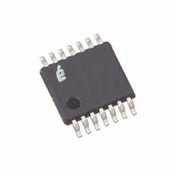
X5329V14T1 Intersil, X5329V14T1 Datasheet - Page 5

X5329V14T1
Manufacturer Part Number
X5329V14T1
Description
IC SUPERVISOR CPU 32K EE 14TSSOP
Manufacturer
Intersil
Type
Simple Reset/Power-On Resetr
Datasheet
1.X5328PZ.pdf
(21 pages)
Specifications of X5329V14T1
Number Of Voltages Monitored
1
Output
Open Drain or Open Collector
Reset
Active High
Reset Timeout
100 ms Minimum
Voltage - Threshold
4.38V
Operating Temperature
0°C ~ 70°C
Mounting Type
Surface Mount
Package / Case
14-TSSOP
Lead Free Status / RoHS Status
Contains lead / RoHS non-compliant
PRINCIPLES OF OPERATION
Power-On Reset
Application of power to the X5328/X5329 activates a
Power-on Reset Circuit. This circuit goes active at
about 1V and pulls the RESET/RESET pin active. This
signal prevents the system microprocessor from start-
ing to operate with insufficient voltage or prior to stabi-
lization of the oscillator. When V
V
RESET/RESET, allowing the processor to begin exe-
cuting code.
Low Voltage Monitoring
During operation, the X5328/X5329 monitors the V
level and asserts RESET/RESET if supply voltage
falls
RESET/RESET signal prevents the microprocessor
from operating in a power fail or brownout condition.
The RESET/RESET signal remains active until the
voltage drops below 1V. It also remains active until
V
V
The X5328/X5329 has a standard V
(V
operating and storage conditions. However, in applica-
tions where the standard V
for
X5328/X5329 threshold may be adjusted.
Setting the V
This procedure sets the V
value. For example, if the current V
the new V
the change. If the new setting is lower than the current
setting, then it is necessary to reset the trip point
before setting the new value.
To set the new V
threshold to the V
pin HIGH. RESET/RESET and SO pins are left uncon-
nected. Then apply the programming voltage V
both SCK and SI and pulse CS LOW then HIGH.
Remove V
TRIP
CC
CC
TRIP
returns and exceeds V
Threshold Reset Procedure
higher
) voltage. This value will not change over normal
value for 200ms (nominal) the circuit releases
below
TRIP
P
and the sequence is complete.
precision
TRIP
is 4.6V, this procedure directly makes
a
TRIP
CC
Voltage
preset
pin and tie the CS pin and the WP
voltage, apply the desired V
in
5
TRIP
TRIP
TRIP
minimum
the
CC
for 200ms.
is not exactly right, or
to a higher voltage
V
exceeds the device
TRIP
TRIP
CC
V
is 4.4V and
TRIP
value,
threshold
.
X5328, X5329
P
TRIP
The
the
CC
to
Figure 1. Set V
Resetting the V
This procedure sets the V
level. For example, if the current V
V
1.7V. This procedure must be used to set the voltage
to a lower value.
To reset the V
2.7 and 5.5V to the V
pin, and the SCK pin HIGH. RESET/RESET and SO
pins are left unconnected. Then apply the program-
ming voltage V
LOW then HIGH. Remove V
complete.
Figure 2. Reset V
TRIP
is reset, the new V
SCK
SCK
SI
CS
SI
CS
V
V
V
V
P
CC
P
P
TRIP
TRIP
P
TRIP
to the SI pin ONLY and pulse CS
TRIP
Voltage
voltage, apply a voltage between
Voltage
CC
Voltage
pin. Tie the CS pin, the WP
TRIP
TRIP
P
is something less than
and the sequence is
to a “native” voltage
TRIP
is 4.4V and the
October 17, 2005
FN8132.1


