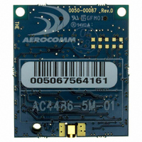
AC4486-5M Laird Technologies, AC4486-5M Datasheet - Page 11

AC4486-5M
Manufacturer Part Number
AC4486-5M
Description
TXRX 868MHZ 3V TTL 5MW RS232
Manufacturer
Laird Technologies
Series
AeroCommr
Specifications of AC4486-5M
Frequency
868MHz
Data Rate - Maximum
115.2kbps
Modulation Or Protocol
FSK
Applications
AMR, Gaming Devices, Inventory Tracking
Power - Output
5mW
Sensitivity
-100dBm
Voltage - Supply
3.3V
Current - Receiving
30mA
Current - Transmitting
40mA
Data Interface
Connector, 2 x 10 Header
Antenna Connector
MMCX
Operating Temperature
-40°C ~ 85°C
Package / Case
Module
Board Size
49 mm x 42 mm x 5 mm
Output Power
5 mW
Antenna
External MMCX Connector
Frequency Rf
869.65MHz
Transmit Power
5mW
Interface Type
Serial
Rohs Compliant
Yes
Lead Free Status / RoHS Status
Lead free / RoHS Compliant
Memory Size
-
Lead Free Status / Rohs Status
Lead free / RoHS Compliant
Available stocks
Company
Part Number
Manufacturer
Quantity
Price
Company:
Part Number:
AC4486-5M
Manufacturer:
Laird Technologies Wireless M2
Quantity:
135
AC4486 Specifications
3.3 S
Care should be taken when selecting transceiver architecture as it can have serious effects on data
rates, latency timings, and overall system throughput. The importance of these three characteristics
will vary from system to system and should be a strong consideration when designing the system.
3.3.1 Serial Interface Data Rate
The Serial Interface Data Rate is programmable by the Host. This is the rate the Host and transceiver
communicate over the serial bus. Possible values range from 1200 bps to 115,200 bps. Note:
Enabling Parity Mode cuts throughput in half and the Interface Buffer size in half. The following
asynchronous serial data formats are supported:
3.3.2 Latency
Note about Timing: The AC4486 is a single frequency radio design. Though it does not hop from one
frequency to another, packet delivery timing is based on a fictitious hop, which occurs every 20ms.
This maximizes the use of the AC4486 resources and makes timing much more deterministic. For
ease of understanding, the documentation will still refer to a hop. The Server will still send a timing
beacon out every 1.2s to provide Clients with its MAC Address.
Acknowledge Mode
The transceiver will use Interface Timeout in conjunction with Fixed Packet Length (whichever
condition occurs first) to determine a complete packet to be sent over the RF. If Full Duplex is
enabled, the transceiver must wait for its appropriate hop (even numbered hops for the Server and
odd numbered hops for the Client). Upon doing this, the transceiver will calculate the amount of time
until the next hop to ensure that it has time to send the packet. If there is enough time, it will send the
packet: if not, it will wait until its next appropriate hop. Transmit Retries and Broadcast Attempts are
handled in the same manner.
Stream Mode
The transceiver will use Interface Timeout in conjunction with Fixed Packet Length (whichever
condition occurs first) to determine a complete packet to be sent over the RF. Next, the transceiver will
begin sending the packet. If a hop is scheduled to occur before the entire packet can be sent out, the
01/21/05
YSTEM
Data Bits
9
8
8
8
7
7
7
T
IMING AND LATENCY
E,O,M,S
E,O,M,S
E,O,M,S
Parity
N
N
N
N
Table 5 – Supported Serial Formats
Stop Bits
1
1
2
1
2
2
1
Transceiver Programming Requirements
Parity Mode disabled
Parity mode disabled
Parity Mode disabled
Parity Mode enabled
Parity Mode enabled
Parity Mode enabled
Parity Mode enabled
11


