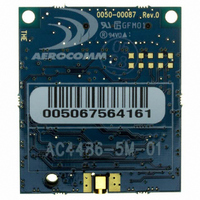
AC4486-5M Laird Technologies, AC4486-5M Datasheet - Page 39

AC4486-5M
Manufacturer Part Number
AC4486-5M
Description
TXRX 868MHZ 3V TTL 5MW RS232
Manufacturer
Laird Technologies
Series
AeroCommr
Specifications of AC4486-5M
Frequency
868MHz
Data Rate - Maximum
115.2kbps
Modulation Or Protocol
FSK
Applications
AMR, Gaming Devices, Inventory Tracking
Power - Output
5mW
Sensitivity
-100dBm
Voltage - Supply
3.3V
Current - Receiving
30mA
Current - Transmitting
40mA
Data Interface
Connector, 2 x 10 Header
Antenna Connector
MMCX
Operating Temperature
-40°C ~ 85°C
Package / Case
Module
Board Size
49 mm x 42 mm x 5 mm
Output Power
5 mW
Antenna
External MMCX Connector
Frequency Rf
869.65MHz
Transmit Power
5mW
Interface Type
Serial
Rohs Compliant
Yes
Lead Free Status / RoHS Status
Lead free / RoHS Compliant
Memory Size
-
Lead Free Status / Rohs Status
Lead free / RoHS Compliant
Available stocks
Company
Part Number
Manufacturer
Quantity
Price
Company:
Part Number:
AC4486-5M
Manufacturer:
Laird Technologies Wireless M2
Quantity:
135
AC4486 Specifications
5.1.4 CTS Handshaking (pin 7)
The AC4486 has an interface buffer size of 256 bytes. If the buffer fills up and more bytes are sent to
the transceiver before the buffer can be emptied, data loss will occur. The transceiver prevents this
loss by asserting CTS High as the buffer fills up and taking CTS Low as the buffer is emptied. CTS On
in conjunction with CTS On Hysteresis control the operation of CTS. CTS On specifies the amount of
bytes that must be in the buffer for CTS to be disabled (High). Even while CTS is disabled, the OEM
Host can still send data to the transceiver, but it should do so carefully. Once CTS is disabled, it will
remain disabled until the buffer is reduced to the size specified by CTS On Hysteresis.
5.1.5 RTS Handshaking (pin 8)
With RTS Mode disabled, the transceiver will send any received packet to the OEM Host as soon as
the packet is received. However, some OEM Hosts are not able to accept data from the transceiver all
of the time. With RTS Mode Enabled, the OEM Host can keep the transceiver from sending it a packet
by disabling RTS (logic High). Once RTS is enabled (logic Low), the transceiver can send packets to
the OEM Host as they are received. Note: Leaving RTS disabled for too long can cause data loss
once the transceiver’s 256 byte receive buffer fills up.
5.1.6 9600 Baud (pin 12)
9600_BAUD – When pulled logic Low before applying power or resetting, the transceiver’s serial
interface is forced to a 9600, 8-N-1 (8 data bits, No parity, 1 stop bit) rate. To exit, the transceiver must
be reset or power-cycled with 9600_Baud logic High. This pin is used to recover transceivers from
unknown baud rates only. It should not be used in normal operation. Instead the transceiver Interface
Baud Rate should be programmed to 9600 baud if that rate is desired for normal operation.
5.1.7 RSSI (pin 13)
Instantaneous RSSI
Received Signal Strength Indicator is used by the Host as an indication of instantaneous signal
strength at the receiver. The Host must calibrate RSSI without a RF signal being presented to the
receiver. Calibration is accomplished by following the steps listed below.
01/21/05
1.
2.
3.
Power up only one Client (no Server) transceiver in the coverage area.
Measure the RSSI signal to obtain the minimum value with no other signal present.
Power up a Server. Make sure the two transceivers separated by approximately ten feet and
measure the Client’s peak RSSI, once the Client reports In Range, to obtain a maximum value at
full signal strength.
39


