AC4486-5M Laird Technologies, AC4486-5M Datasheet - Page 48
AC4486-5M
Manufacturer Part Number
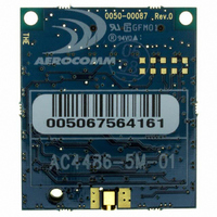
AC4486-5M
Description
TXRX 868MHZ 3V TTL 5MW RS232
Manufacturer
Laird Technologies
Series
AeroCommr
Specifications of AC4486-5M
Frequency
868MHz
Data Rate - Maximum
115.2kbps
Modulation Or Protocol
FSK
Applications
AMR, Gaming Devices, Inventory Tracking
Power - Output
5mW
Sensitivity
-100dBm
Voltage - Supply
3.3V
Current - Receiving
30mA
Current - Transmitting
40mA
Data Interface
Connector, 2 x 10 Header
Antenna Connector
MMCX
Operating Temperature
-40°C ~ 85°C
Package / Case
Module
Board Size
49 mm x 42 mm x 5 mm
Output Power
5 mW
Antenna
External MMCX Connector
Frequency Rf
869.65MHz
Transmit Power
5mW
Interface Type
Serial
Rohs Compliant
Yes
Lead Free Status / RoHS Status
Lead free / RoHS Compliant
Memory Size
-
Lead Free Status / Rohs Status
Lead free / RoHS Compliant
Available stocks
Company
Part Number
Manufacturer
Quantity
Price
Company:

Part Number:
AC4486-5M
Manufacturer:
Laird Technologies Wireless M2
Quantity:
135


AC4486 Specifications
Interface Options
Modem Mode – Full modem handshaking is supported by the transceivers when enabled in EEPROM.
Modem Mode is incompatible with RS-485 DE mode. Because Command/Data performs an alternate
function when this mode is enabled, CC on-the-fly commands cannot be used and Configuration
Mode is entered by forcing 9600 baud through the 9600_BAUD pin. Therefore, modem mode, though
enabled in EEPROM, will be ignored when 9600 baud is forced. Both modem interfaces are shown
below.
RS-485 DE Control – When enabled in EEPROM, the transceiver will use the GO0 pin to control the DE
pin on external RS-485 circuitry. If enabled, when the transceiver has data to send to the host, it will
assert GO0 Low, send the data to the host, and take GO0 High.
01/21/05
DCE Pin
Number
DTE Pin
Number
1
2
3
4
5
6
7
8
9
1
2
3
4
5
6
7
8
9
When Interfacing the AC4486 to a DCE (Data Communications Equipment):
When Interfacing the AC4486 to a DTE (Data Terminal Equipment):
Table 14 – Transceiver Interface to DCE (Server Transceiver)
Table 15 – Transceiver Interface to DTE (Client Transceiver)
DCE Pin
DTE Pin
Name
Name
DCD
GND
GND
RXD
DTR
DSR
DCD
RXD
DSR
TXD
RTS
CTS
TXD
DTR
RTS
CTS
RI
RI
Direction with
Direction with
Transceiver
Transceiver
Respect to
Respect to
Out
Out
Out
Out
Out
Out
Out
Out
In
In
In
In
In
In
In
In
AC4486 Pin Name
AC4486 Pin Name
Command/Data
Hop Frame
GO0
RXD
GO1
TXD
RTS
CTS
RXD
GO0
CTS
RTS
TXD
GI0
GI1
GI0
AC4486 Pin
AC4486 Pin
Number
Number
14
17
1
2
3
4
5
6
8
7
9
1
5
7
8
3
2
4
48
Related parts for AC4486-5M
Image
Part Number
Description
Manufacturer
Datasheet
Request
R

Part Number:
Description:
TXRX 868MHZ 3V TTL 5MW RS232
Manufacturer:
Laird Technologies
Datasheet:

Part Number:
Description:
TXRX 868MHZ 3V TTL 5MW RS485
Manufacturer:
Laird Technologies
Datasheet:
Part Number:
Description:
TXRX 868MHZ 3V TTL 5MW RS485
Manufacturer:
Laird Technologies
Datasheet:

Part Number:
Description:
Bluetooth Serial Module Development Kit
Manufacturer:
Laird Technologies
Part Number:
Description:
BLUETOOTH MODULE DEVELOPMENT KIT
Manufacturer:
Laird Technologies
Part Number:
Description:
Bluetooth 2.0 AT Data Module, Internal Antenna Development Kit
Manufacturer:
Laird Technologies

Part Number:
Description:
BLUETOOTH EVAL BOARD BTM511
Manufacturer:
Laird Technologies
Datasheet:

Part Number:
Description:
Bluetooth / 802.15.1 Modules & Development Tools BLUETTH Multimed MODLE, No ANT DEVKIT
Manufacturer:
Laird Technologies
Datasheet:

Part Number:
Description:
DEV KIT PRM122
Manufacturer:
Laird Technologies
Datasheet:
Part Number:
Description:
DEV KIT PRM123
Manufacturer:
Laird Technologies
Datasheet:

Part Number:
Description:
CHOKE COMMON MODE 110 OHMS SMD
Manufacturer:
Laird Technologies
Datasheet: