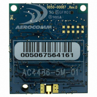
AC4486-5M Laird Technologies, AC4486-5M Datasheet - Page 43

AC4486-5M
Manufacturer Part Number
AC4486-5M
Description
TXRX 868MHZ 3V TTL 5MW RS232
Manufacturer
Laird Technologies
Series
AeroCommr
Specifications of AC4486-5M
Frequency
868MHz
Data Rate - Maximum
115.2kbps
Modulation Or Protocol
FSK
Applications
AMR, Gaming Devices, Inventory Tracking
Power - Output
5mW
Sensitivity
-100dBm
Voltage - Supply
3.3V
Current - Receiving
30mA
Current - Transmitting
40mA
Data Interface
Connector, 2 x 10 Header
Antenna Connector
MMCX
Operating Temperature
-40°C ~ 85°C
Package / Case
Module
Board Size
49 mm x 42 mm x 5 mm
Output Power
5 mW
Antenna
External MMCX Connector
Frequency Rf
869.65MHz
Transmit Power
5mW
Interface Type
Serial
Rohs Compliant
Yes
Lead Free Status / RoHS Status
Lead free / RoHS Compliant
Memory Size
-
Lead Free Status / Rohs Status
Lead free / RoHS Compliant
Available stocks
Company
Part Number
Manufacturer
Quantity
Price
Company:
Part Number:
AC4486-5M
Manufacturer:
Laird Technologies Wireless M2
Quantity:
135
AC4486 Specifications
Stream Mode
In Broadcast Stream mode, the RF packet is broadcast out to all eligible receivers on the network. In
Addressed Stream Mode, the RF packet is sent out to the receiver designated by the Destination
Address. The sending transceiver will send each RF packet out once. There are no retries on the
packet. Whether or not the packet contains errors, the receiver(s) will send the packet to the OEM
Host. In fact, if only part of the packet is able to be received, the transceiver will still send the partial
packet to the OEM Host. Note: Stream Mode is incompatible with Full Duplex Mode.
5.2.3 Sub Hop Adjust
Sub Hop Adjust is an AC4486 protocol parameter and should only be modified at the recommendation
of Aerocomm.
5.2.4 Duplex Mode
In Half Duplex mode, the AC4486 will send a packet out over the RF when it can. This can cause
packets sent at the same time by a Server and a Client to collide with each other over the RF. To
prevent this, Full Duplex Mode can be enabled. This mode restricts Clients to transmitting on odd
numbered frequency “bins” and the Server to transmitting on even frequency bins. Though the RF
hardware is still technically half duplex, it makes the transceiver seem full duplex. This can cause
overall throughputs to be cut in half. Note: All transceivers on the same network must have the same
setting for Full Duplex. Full Duplex mode is incompatible with Stream RF mode.
5.2.5 Interface Timeout/RF Packet Size
Interface Timeout, in conjunction with RF Packet Size, determines when a buffer of data will be sent out
over the RF as a complete RF packet based on whichever condition occurs first.
Interface Timeout – Interface Timeout specifies a maximum byte gap between consecutive bytes.
When that byte gap is exceeded, the bytes in the transmit buffer are sent out over the RF as a
complete packet. Interface timeout is adjustable in 0.5ms increments and has a tolerance of ±0.5ms.
Therefore, the Interface Timeout should be set to a minimum of 2. The default value for Interface
Timeout is 4 or 2ms.
RF Packet Size – When the amount of bytes in the transceiver transmit buffer equals RF Packet Size,
those bytes are sent out as a complete RF packet. Every packet the transceiver sends over the RF
contains extra header bytes not counted in the RF Packet Size. Therefore, it is much more efficient to
send a few large packets than to send many short packets. However, if RF Packet size is set too large
and Acknowledge Mode is enabled, the transceiver will not be able to send any packets because
Acknowledge Mode requires the entire RF packet to be sent in the same hop whereas Stream Mode
packets can span multiple hops.
01/21/05
43


